MANUAL - SPRAY GUN CLEANERS - UG7500 SERIES
REVISION 2011-05
6
•
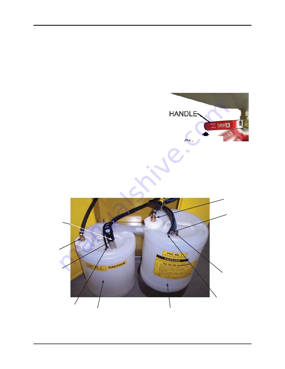
Inside the cabinet you will see two pipes strapped together, the Suction Pipe and the Rinse
Pump. Cut the strap holding them together.
Do not cut
the other straps holding the black and
blue tubes.
•
Disconnect the Suction Pipe from the Drain Valve by pushing the gray button and bring both
pipes outside of the cabinet.
•
Insert the Rinse Pump into the full pail on the right and the Suction Pipe into the pail with 3 gal
on the left. Insert the Manual Wash Suction Tube into the lid of the left (wash) pail, as shown.
Insert the Manual Rinse Suction Tube through the lid of the right (rinse) pail, as shown.
•
Move the pails into the cabinet and re-connect the
Suction Pipe of the left pail to the Drain Valve.
GROUND WIRE INSTALLATION
•
Three ground wires are provided to discharge static
electricity. To work properly, all three must be installed
correctly. Connect the two ground wires inside the cabi-
net to Suction Pipe and to Rinse Pump and the wire on
the outside back of the cabinet to an external grounded
object.
OPERATION
PRE - CLEAN
• Disconnect the spray gun from the air hose. Pour paint from the cup (when present) into a 5
gallon pail (not supplied).
Drain Valve
PAIL NO.2
WASH SOLVENT
780-8110P
MANUAL WASH
SUCTION TUBE
SUCTION PIPE
ASSEMBLY
PAIL NO. 1
CLEAN SOLVENT
780-8120P
MANUAL RINSE
SUCTION TUBE
RINSE PUMP
ASSEMBLY
GROUND WIRE
GROUND WIRE
TRANSFER
HOSE OUT
TRANSFER
HOSE IN
Note: The “NG” model has a Stainless Steel Pail Set, see page 16.


