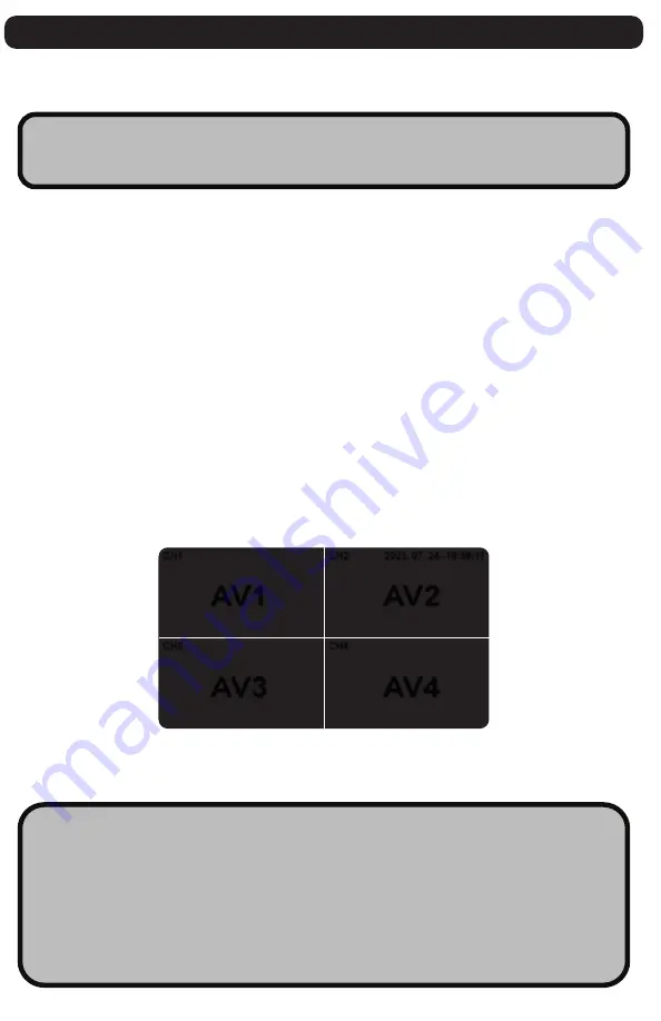
CH1
CH3
CH2
CH4
2023. 07. 24--18:58:11
AV1
AV2
AV3
AV4
Installation Guide
The
CM-BM0711
will only work with products listed in the [
Component List
]
on (pg 1).
STEP 1:
Choose your desired monitor and camera locations based on safety
procedures.
STEP 2:
Feed all cables through the vehicle. If required, drill a [20mm or
0.8”] hole for passing cables through vehicle walls and install split grommets
where applicable. Split grommets are provided with the cameras.
STEP 3:
Perform a function test by connecting the system together. If any
issues appear or the system is not operating properly, see troubleshooting
on (pg 6).
STEP 4:
Connect the (RED) 12V to 24V POWER wire to any 12V to 24V power
source and (BLACK) GROUND wire to chassis ground. This will now power the
entire system and all cameras. - refer to (pg.3) Wiring Diagram
STEP 5:
Connect your (
CM-BC0200H / CM-BC0200HV
) cameras to each of the
individual AV connections (AV1, AV2, AV3, AV4). The monitor should show each
camera in operation once connected. - refer to (pg.3) Wiring Diagram
STEP 6:
Connect the trigger wires appropriately to each operation on the
vehicle. - refer to (pg.3) Wiring Diagram
WARNING!!
KEEP ALL CABLES AWAY FROM HOT OR MOVING
PARTS THAT COULD CAUSE ELECTRICAL INTERFERENCE
What is a TRIGGER WIRE?
A trigger wire when connected will take priority on the monitor
when the associated vehicle function is triggered.
For example, if you connect
(GREY) CAM 1 - TRIGGER WIRE
to the
vehicle’s backup function,
CAMERA 1 - AV1
will take precedence
when reversing, assuming you positioned this camera as the backup.
Only
[
CAMERA 1 - AVI 1
]
has Audio
4


