


Service Manual
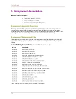
3. Component Assemblies
What’s in this Chapter:
•
Component Assembly Overview
•
Component Replacement Kits
•
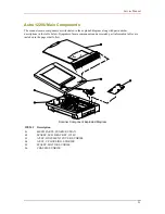
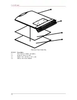
Scanner Component Exploded Diagrams
Component Assembly Overview
Drawings of
Astra 1220U
replacement part kits and exploded diagrams of scanner components are
provided in this chapter along with quantity and part number information to assist you in ordering
replacement parts and help you determine the best way to disassemble and assemble the scanner. When
ordering parts, be sure to include the part numbers referred to in the tables and drawings.
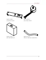
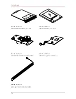
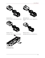
Component Replacement Kits
Component kits are listed in the tables below with component kit drawings provided on the following
pages. When ordering replacement kits, be sure to include associated part numbers with your purchase
order(s).
Astra 1220U Replacement Kits
(For Astra 1220Umodel scanners only)
Part No
Description
030028-01 KIT,M/B
PLATE,1220U
030032-13
KIT, MOTOR, 35DX16T
030072-55 KIT,CARTON,KTX-TAU
030104-23
KIT,FLAT CABLE,24P,NO SHIELDING
030201-08
KIT,DOCUMENT COVER,Astra 1220
030202-16
KIT,UP HOUSING,Astra 1220
030203-09
KIT,MOTOR A'SSY,35Dx16T,W/O CORE
030205-05 KIT,INV,2.6¢x250x1,S12III,Garear
030206-10 KIT,LAMP
A'SSY,COLD-CATHODE
030519-12
KIT, SPS, 100-240V, 12VDC, UK, PLUG CORE
030519-13
KIT, SPS, 100-240V, 12VDC, ASTRL, PLUG CORE
030519-14 KIT,SPS,100-240V,12Vdc,USA,PLUG
CORE
030519-15 KIT,SPS,200-240V,12Vdc,1A,EUR,PLUGIN
030602-04 KIT,CHASSIS
A'SSY
030742-00
KIT,WIRE LED,Astra 1220P
030743-01 KIT,PCBA,M/B,1220U
030788-00
KIT, CABLE, USB, A TOB, 1.5M, CORE
*Note: Drawings of these scanner parts are included in this chapter.
16
Summary of Contents for Astra 1220U
Page 1: ...Astra 1220U Color Scanner Service Manual UMAX Data Systems Inc 0898 e...
Page 4: ...Pin Assignment 44 iv...
Page 14: ...Service Manual AD Pin Assignment 10...
Page 15: ...Service Manual Motor and To CCD Board Pin Assignment 11...
Page 16: ...Service Manual Power Code Pin Assignment 12...
Page 17: ...Service Manual EPP to USB Bridge Pin Assignment 13...
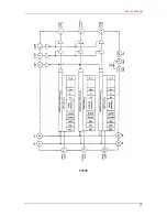
Page 19: ...Service Manual 3797P 15...
Page 37: ...Service Manual Appendix B Scanner Outline Diagram 312 83 98 471 33...


