background image


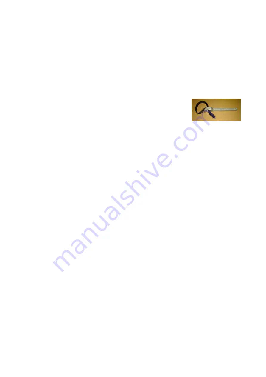
Belt wrench


BW-2

by Supertool Inc.


10-7.

Turn on the power source of the UFO-003, and operate for   

a few minutes. Drain all the oil inside.


10-8.

Stop operating after making sure that draining stops 
from the drain port. 

10-9.

Loosen the upper joint of the filter case and remove   

the hose. 

10-10.

Remove the filter case by turning it anti-clockwise.


If it is stiff, put rubber bands three places   

around the case and turn it. It is also easy to turn it   
by usin

g a belt wrench. Should not use any other 

tools for removing; it might cause damages). 

10-11.Remove the element from the housing head. 

10-12.After cleaning the inside and outside of the housing 
      area, place a new element. 
10-13.Install the filter case and the hose. 
10-14.Install a plug to the drain port.(Be sure to fix with the seal tape around screw area). 
10-15.Supply some oil by following the directions on Section 6-2

6-7. 


Caution

) 

If the oil is badly degraded, and frequent replacement 

of the element is needed, a drain valve (optional) is 
very useful.


11.

Oil Replacement of Vacuum Pump


11-1. For oil draining of the vacuum pump

follow the directions on Section 

10-2 to 10-8. The Inlet side 3-way valve should face to the 
inlet side.

The Outlet side 3-way valve is at closed position


11-2. For supplying oil into the vacuum pump, follow the directions on 
    Section 6-2 to 6-7 


Summary of Contents for UFO-003

Page 1: ...ANUAL ULVAC KIKO Inc Important Before Operating the UFO 003 small size oil filtration be sure to read this instruction manual thoroughly to ensure efficient and safe operation Size or Specifications o...

Page 2: ...ults from the pump being stopped for a long time 2 Foreign objects have built up in the circulator pump from circulating extremely contaminated oil 1 Rust tends to form while the circulating pump is s...

Page 3: ...rved in this instruction manual and the warning labels on this product marks symbols are categorized as follows DANGER DANGER indicates major hazardous situations which present an immediate threat of...

Page 4: ...e oil leakage or explosion WARNING Do not cut an element fiber nor process adhesives etc It will loose a fiber shape and will not function as the element WARNING If the fiber element got in your eyes...

Page 5: ...tions for Operation Please observe the following conditions for storage installation and operation Ambient temperature and humidity during operation 7 40 C Temperature on the surface during operation...

Page 6: ...or damages on the pump DANGER Do not give any outer pressure or not handle the element roughly It will cause deform due to a fiber shaping product DANGER Install the element on the main body tightly...

Page 7: ...low system diagram P5 Installation P6 Preparation for Operation and Supplement P6 Operation P7 Shutdown P7 Maintenance Check P7 Replacement of Element P8 Oil Replacement of Vacuum Pump P9 Troubleshoot...

Page 8: ...iltration Circulating Filtration type Capacity of Filtration 0 6 0 7 L min 50 60Hz Maximum capacity of water removal 300cc Water disposal precision below 100ppm Maximum acid neutralization ability 0 4...

Page 9: ...Description of 3 ways valve Inlet side 3 way valve direction Refill port side Closed position Inlet port side Outlet side 3 way valve direction Upper side oil drain side Closed position Drain port sid...

Page 10: ...4 3 Outside view Item No Name Filter case Element Housing head Pressure gauge Power switch Stage Inlet 3 ways valve Inlet Inlet port Outlet side 3 way valve Outlet Drain port plug...

Page 11: ...port inlet side 3 ways valve outlet side 3 ways valve outlet inlet Drain port optional special adapter is required UFO 003 Type Oil filtration system How to connect with GLD series pump attachment hos...

Page 12: ...t the unit to the oil rotary pump by following the procedure on Section 4 1 Install the attached hose nipple tubes into both the oil inlet and oil drain port of the GCD series 2 Connect the inlet to t...

Page 13: ...1 Turn off the main switch 8 2 Close both the Inlet side 3 way valve and Outlet side 3 way valve neutral position The Inlet side 3 way valve faces upward the Outlet side 3 way valve places sideways C...

Page 14: ...nded Due to its highly sophisticated assembly please contact ULVAC KIKO or our dealers for the overhaul 9 3 List of consumable supplies Name qty Element Pump connection hose O ring AS 238 O ring G 100...

Page 15: ...t from the housing head 10 12 After cleaning the inside and outside of the housing area place a new element 10 13 Install the filter case and the hose 10 14 Install a plug to the drain port Be sure to...

Page 16: ...Clean the pipe Piping Defect in piping Check the pipe and repair Pump lock Check the pump and repair Defect in rotor Repair the pump Defect in oil seal Repair the pump Circulating pump Defect in reli...

Page 17: ...pump Valve Hose Special quality of material AS resin PE resin SUS stainless steel PE polyethylene BS brass FC 250 steel casing BS PVC 13 2 Anti solvent Anti chemicals summary No problem Caution Aceton...

Page 18: ...ient temperature for operation 7 to 40 Type of exhaust gas of vacuum pump and temperature Dry air 7 to 40 Used and operated in accordance with the instructions manual These cases listed below should b...

Page 19: ...Situation Abnormal Sound Wrong Pressure Malfunction Others Periodical Inspection Periodical Repair Others 2 What kind of gas the pump sucked Is the gas toxic Yes No The kind and name of the gas 3 How...

Reviews: