background image

Installation and Maintenance Manual 

ULTRAFLEX


page 12 

of 47

- TIE BAR A97

ENGLISH

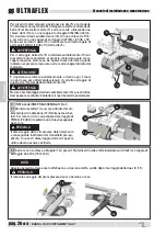
5  BAR CONNECTION TO THE CENTRAL ENGINE
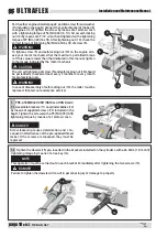
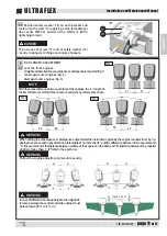
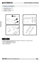
Connect each end piece to the corresponding connec-
tor of bracket A on the central engine by means of a 
screw, a washer and a self-locking M6 nut (supplied 
in bag F) using the 10 mm and 16 mm wrenches with 
a tightening torque of 8.5 Nm (6.27 lb ft).

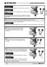
6  Once operation 5 has been completed, in order to avoid accidental changes to the bars, they must be locked 

by tightening ring nut (18) using a 22 mm wrench with a tightening torque of 40 [Nm] (29.52 [lb ∙ ft]) by means 

of a second wrench on the end element (19).

WARNING

DO NOT FORCE THE UNSCREWING OF THE BAR'S END WHEN REACHING THE MAXIMUM EXTENSION.

DANGER

FORCING THE UNSCREWING OF THE BAR'S END WILL IRRETRIEVABLY DAMAGE THE BAR.

NOTE

Be careful not to damage the exposed thread: dents on the thread cause seizure of the parts.

NOTE

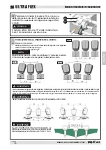
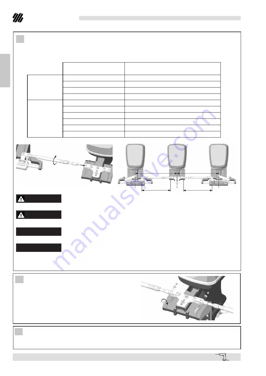
The correlation of the distance between centers is L2 or L3 and the bar length depends on the chosen diver-

gence or convergence angle.

L1

L1

L

L

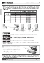
4.2  Adjust the length of each pre-assembled unit by holding the free end piece of the bar still and rotating 

(manually or with a 22 mm wrench) the central piece of the bar until the hole of the end piece is aligned with 

the hole of the connector on the bracket of the central engine according to the distance between centers L1 

of the engines.

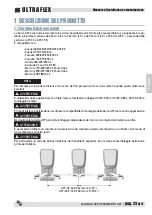
DISTANCE BETWEEN 

CENTERS OF THE ENGINES

APPROXIMATE LENGTH OF THE BAR L

A97 - 30:

26" - 30.5"

660 - 762 mm

26’’

481 mm (19’’) 

27’’

507 mm (20’’)

28’’

532 mm (21’’)

29’’

558 mm (22’’)

A97 -35.5:

30" -  35.5"

762 - 900 mm

30’’

583 mm (23’’)

31’’

609 mm (24’’)

32’’

634 mm (25’’) 

33’’

659 mm (26’’) 

34’’

685 mm (27’’)

35.5’’

722 mm (28.5’’)

Summary of Contents for A97

Page 1: ...A97 TIE BAR Installation and Maintenance manual ITALIANO FRAN AIS ENGLISH ULTRAFLEX R IT EN FR page 2 pag 17 page 33 Dr Dis Des n 35512 a 05 03 2021 PARTNER...

Page 2: ...intain and improve the quality standards constantly pursue a continuous process improvement to meet the market needs and to increase the customer satisfaction ULTRAFLEX Environmental Management System...

Page 3: ...S 7 1 2 PACKAGING CONTENTS 8 TABLE OF CONTENTS SECTION 3 MAINTENANCE 3 1 ORDINARY MAINTENANCE 14 3 2 EXTRAORDINARY MAINTENANCE 14 SECTION 2 INSTALLATION 2 1 NECESSARY TOOLS 9 2 2 A97 INSTALLATION 9 SE...

Page 4: ...Installation and Maintenance Manual ULTRAFLEX page 4 of 47 TIE BAR A97 ENGLISH DOCUMENT REVISIONS Rev Rev Date Date Revision description Revision description 0 18 12 2020 First edition...

Page 5: ...al Immediate hazards which CAUSE severe personal injury or death The symbol aside indicates all the operations which must be carried out by qualified or skilled staff in order to avoid hazards We reco...

Page 6: ...FLEX S r l Via Milite Ignoto 8A 16012 Busalla GE Italy Tel 39 010 962 01 Email service ultraflexgroup it www ultraflexgroup it North South Central America UFLEX USA 6442 Parkland Drive Sarasota FL 342...

Page 7: ...rstroke Mercury OPTIMAX V6 NOTE The distance between the centers is calculated between the centers of the holes located in the engine tiller arms when the engines are parallel It can be used in applic...

Page 8: ...ing contents 1 Pre assembled bars A B and C 2 Bag D with screws 3 Bag E with bracket and screws 4 Bag F with screws NOTE The bag number 3 bag E must be used only with the following engines Mercury 175...

Page 9: ...s necessary to assemble the bracket 1 on the central engine arm by positioning the screws 5 16 UNF 2 and by putting the washers 3 between the bracket and the screws All these elements are included in...

Page 10: ...Nm 20 lb x ft After tightening nut 10 check the correct torque of tightening 54 Nm 40 lb x ft of screw 5 WARNING To tighten screw 5 and self locking nut 10 on the engine arm ask your motor mechanic w...

Page 11: ...samedistancebetweencentersoftheengines the L lengthof thebarwillvaryaccordingtothechosenconvergenceordivergenceangle 4 BAR LENGTH ADJUSTMENT L2 L2 L3 L3 L1 L1 FIG 2 FIG 3 FIG 1 WARNING When setting th...

Page 12: ...NG THE UNSCREWING OF THE BAR S END WILL IRRETRIEVABLY DAMAGE THE BAR NOTE Be careful not to damage the exposed thread dents on the thread cause seizure of the parts NOTE The correlation of the distanc...

Page 13: ...djustment of the bar length 7 3 Once the adjustment has been carried out tighten again ring nut 18 using a 22 mm wrench with a tightening torque of 40 Nm 29 52 lb ft by means of a second wrench on the...

Page 14: ...plications please contact our technical support personnel See paragraph Introduction 2 Periodically wash the components with fresh water in order to remove any salt deposits A B C D E F G H Poor insta...

Page 15: ...H ULTRAFLEX 4 DISMANTLING 4 1 Dismantling When for any reason the system is put out of service it is necessary to follow some rules in order to respect the environment Sheaths pipelines plastic or non...

Page 16: ...Installation and Maintenance Manual ULTRAFLEX page 16 of 47 TIE BAR A97 ENGLISH NOTES...

Page 17: ...BARRA D ACCOPPIAMENTO Manuale di installazione e manutenzione ULTRAFLEX R SOCIO A97...

Page 18: ...gli standard di qualit perseguire un continuo miglioramento dell efficacia e dell efficienza dei processi per poter essere sempre in sintonia con le esigenze del mercato ed accrescere la soddisfazione...

Page 19: ...2 CONTENUTO IMBALLO 24 INDICE GENERALE SEZIONE 3 MANUTENZIONE 3 1 MANUTENZIONE ORDINARIA 30 3 2 MANUTENZIONE STRAORDINARIA 30 SEZIONE 2 INSTALLAZIONE 2 1 UTENSILI NECESSARI 25 2 2 INSTALLAZIONE A97 2...

Page 20: ...one e manutenzione ULTRAFLEX pag 20 di 47 BARRA D ACCOPPIAMENTO A97 ITALIANO INDICE DELLE REVISIONI DEL DOCUMENTO Rev Rev Data Data Descrizione della revisione Descrizione della revisione 0 18 12 2020...

Page 21: ...rmini nautici contenuti nel presente manuale Danni immediati che CAUSANO ferite gravi alla persona o che portano alla morte Le operazioni per la cui esecuzione si richiede onde evitare possibili risch...

Page 22: ...NICA LETTERA INFORMATIVA UFLEX S r l Via Milite Ignoto 8A 16012 Busalla GE Italia Tel 39 010 962 01 Email service ultraflexgroup it www ultraflexgroup it Nord Sud Centro America UFLEX USA 6442 Parklan...

Page 23: ...interasse si intende la distanza tra i centri dei fori presenti sui bracci dei motori quando questi ultimi sono paralleli AVVERTENZA utilizzabile nelle applicazioni con triplo motore fuoribordo e dopp...

Page 24: ...l imballo 1 Preassemblati barra A B e C 2 Sacchetto D con viterie 3 Sacchetto E con staffa e viterie 4 Sacchetto F con viterie NOTA Il sacchetto numero 3 sacchetto E da utilizzarsi unicamente con i se...

Page 25: ...AZIONE STAFFA A Nel caso dei motori Mercury elencati a pag 24 occorre montare la staffa 1 sul braccio del motore centrale posizionando le viti 2 5 16 UNF ed interponendo le rondelle 3 elementi tutti f...

Page 26: ...ppia di serraggio di 27 Nm 20 lb x ft Dopo aver serrato il dado 10 riverificare la corretta coppia di serraggio 54 Nm 40 lb x ft della vite 5 AVVERTENZA Per il serraggio della vite 5 e del dado autobl...

Page 27: ...i interasse tra i motori la lunghezza L della barra varier in funzione dell angolo di convergenza o divergenza scelto 4 REGOLAZIONE DELLA LUNGHEZZA DELLA BARRA L2 L2 L3 L3 L1 L1 FIG 2 FIG 3 FIG 1 AVVE...

Page 28: ...MASSIMA ESTENSIONE PERICOLO FORZARE LO SVITAMENTO DEI PUNTALI DANNEGGERA IRREPARABILMENTE LA BARRA NOTA Fare attenzione a non danneggiare la filettatura esposta ammaccature sulla filettatura provocano...

Page 29: ...regolazione stringere nuovamente la ghiera 18 utilizzando una chiave da 22 mm con una cop pia di serraggio di 40 Nm 29 52 lb ft aiutandosi con una seconda chiave sull elemento di estremit 19 AVVERTENZ...

Page 30: ...5 Nm 70 lb ft D 3 Nm 2 lb ft E 40 Nm 29 52 lb ft F Vedere punto 6 capitolo 2 2 G Vedere punto 6 capitolo 2 2 H 24 6 Nm 18 14 lb ft Nel caso di smontaggio dei dadi autobloccanti e degli elementi C e H...

Page 31: ...Smantellamento Qualora si intenda per qualsiasi motivo mettere fuori servizio la barra di accoppiamento necessario os servare alcune regole fondamentali atte a salvaguardare l ambiente Guaine condotti...

Page 32: ...Manuale di installazione e manutenzione ULTRAFLEX pag 32 di 47 BARRA D ACCOPPIAMENTO A97 ITALIANO NOTE...

Page 33: ...BARRE D ACCOUPLEMENT Manuel d installation et d entretien ULTRAFLEX R ASSOCIE A97...

Page 34: ...liorer continuellement les standard de qualit poursuivre une am lioration continue de l efficacit des processus afin de r pondre toujours aux exi gences du march et d augmenter la satisfaction des Cli...

Page 35: ...ERALES 39 1 2 CONTENU EMBALLAGE 40 INDEX GENERAL SECTION 3 ENTRETIEN 3 1 ENTRETIEN ORDINAIRE 46 3 2 ENTRETIEN EXTRAORDINAIRE 46 SECTION 2 INSTALLATION 2 1 OUTILS NECESSAIRES 41 2 2 INSTALLATION A97 41...

Page 36: ...ation et d entretien ULTRAFLEX page 36 de 47 BARRE D ACCOUPLEMENT A97 FRAN AIS INDEX DES REVISIONS DU DOCUMENT R v R v Date Date Description de la r vision Description de la r vision 0 18 12 2020 Prem...

Page 37: ...personne ou qui en provoquent la mort Les op rations pour l ex cution desquelles on demande du personnel qualifi ou sp cialis afin d viter toute sorte de risques sont indiqu es avec le sym bole c t On...

Page 38: ...ETTRE D INFORMATION UFLEX S r l Via Milite Ignoto 8A 16012 Busalla GE Italia Tel 39 010 962 01 Email service ultraflexgroup it www ultraflexgroup it Am rique du nord du sud centrale UFLEX USA 6442 Par...

Page 39: ...stance entre axes est la distance entre les centres des trous pr sents sur les bras des moteurs quand ils sont parall les AVERTISSEMENT Elle peut tre utilis e dans les applications avec moteur hors bo...

Page 40: ...Contenu emballage 1 Composants pr assembl s barre A B et C 2 Sac D avec vis 3 Sac E avec trier et vis 4 Sac F avec vis NOTE Le sac num ro 3 sac E doit tre utilis seulement avec les moteurs suivants Me...

Page 41: ...16 mm 2 INSTALLATION ETRIER A Dans le cas des moteurs Mercury list s la page 40 il faut assembler l trier 1 sur le bras du moteur central en positionnant les vis 5 16 UNF 2 et en interposant les ronde...

Page 42: ...lb x ft Apr s avoir serr l crou 10 v rifier de nouveau le couple de serrage correct 54 Nm 40 lb x ft de la vis 5 AVERTISSEMENT Pour serrer la vis 5 et l crou autofrein 10 sur le bras moteur demander v...

Page 43: ...distanceentre axesdesmoteurs lalongueur L delabarre variera en fonction de l angle de convergence ou de divergence choisi 4 REGLAGE DE LA LONGUEUR DE LA BARRE L2 L2 L3 L3 L1 L1 FIG 2 FIG 3 FIG 1 AVERT...

Page 44: ...XIMALE DANGER FORCER LE DEVISSAGE DES EMBOUTS PEUT ENDOMMAGER IRREMEDIABLEMENT LA BARRE NOTE Faire attention ne pas endommager le filetage expos des bosselures sur le filetage provoquent du grip page...

Page 45: ...lage effectu serrer de nouveau le collier 18 l aide d une cl de 22 mm avec un couple de serrage de 40 Nm 29 52 lb ft en utilisant une deuxi me cl sur l l ment d extr mit 19 AVERTISSEMENT V rifier s il...

Page 46: ...70 lb ft D 3 Nm 2 lb ft E 40 Nm 29 52 lb ft F Voir point 6 paragraphe 2 2 G Voir point 6 paragraphe 2 2 H 24 6 Nm 18 14 lb ft Au cas o les crous autofrein s et les l ments C et H voir les figures au d...

Page 47: ...lition Si la barre d accouplement doit tre mise hors service pour quelques raisons que ce soit les r gles fondamen tales suivantes doivent tre observ es pour la protection de l environnement Gaines co...

Page 48: ...ULTRAFLEX S p A 16015 Casella Genova Italia Via Crose 2...

Reviews: