


Ultimatte-9 Operations Manual
March 1, 2000
5
The outputs are in 4:2:2:4 format though all internal processing is done in 4:4:4:4 format.
Scan line rate (525 / 625) selection is automatic, and there are no adjustments for H and V
blanking. Ancillary data present in the H and V Blanking interval of the Reference signal is passed
to the output, while the information present in the H and V Blanking interval of BG and External
Matte signals are blanked.
5. Communications
Communication between the Main Unit and the Smart Remote is through an RS-422 interface at
a data rate of 115 Kbps. A standard DB9 male-male RS-422 cable is needed, with a maximum
length not exceeding 1 Km (pins 3,8 and 7,2 are used). A maximum of four (4) Ultimatte-9 Main
Units can be connected to one Smart Remote.
The Smart Remote is software configured to be the Master with up to four (4) Ultimatte-9 Main
Units as slaves. Only the Master can initiate a message exchange. The Ultimatte-9 Main Unit is
shipped with a factory default ID of number 1. When more than one unit needs to be connected,
each should be assigned a different number. Each Main Unit will respond only when it is
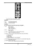
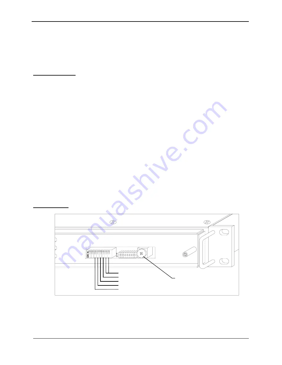
addressed. The ID number is selected through the rotary switch (the selected number should be
aligned to the 9 o’clock position).
NOTE: It is necessary to re-cycle power for ID settings to take effect.
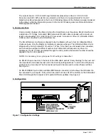
An RS-422 loop connector on the back of the Ultimatte-9 permits "daisy chaining" to the next unit.
It is important to terminate the last unit in the chain by setting switches 7 and 8 to the ON (down)
position on the main board. The front panel will need to be removed to access these switches.
See Figure 1.
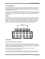
An RS-232/RS422 port is also available (DB9 female connector), which allows the Ultimatte-9 to
be connected to a computer. This port can be used to access all of the controls on the Ultimatte-9
Main Unit through the computer and to upload software updates. See Figure 2.
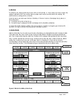
6. Configuration
Figure 1: Configuration Settings
I.D. 1-4
#1 SELECTED
AS SHOWN
RS-422 TERMINATOR
EDITOR RS422 / 232
LOAD LCA MODULES
REPROGRAM UP FLASH MEMORY
SET FACTORY DEFAULTS
3 4
7
6
5
1 2
8
21
0
4 5
67
8
3
9


