


6 GB/IE/NI
Hydraulic Trolley Jack
Introduction
We congratulate you on the purchase
of your new product. You have chosen
a high quality product. The instructions
for use are part of the product. They contain im-
portant information concerning safety, use and
disposal. Before using the product, please famil-
iarise yourself with all of the safety information
and instructions for use. Only use the product as
described and for the specified applications. If
you pass the product on to anyone else, please
ensure that you also pass on all the documenta-
tion with it.
Proper use
The hydraulic vehicle jack is intended for raising
and lowering motor vehicles. Other uses or
modification of the hydraulic vehicle jack shall
be considered as improper use and may lead
to injury or damage. The manufacturer will not
accept liability for loss or damage arising from
improper use. The product is not intended for
commercial use.
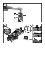
Note:
Reclose the release valve
5
after each
use!
Description of parts
1
Lifting handle
2
Lifting arm
3
Support plate
4
Carrying handle
5
Release valve
6
Lifting handle socket
7
Cover
8
Relief valve
9
Adapter
10
Hex bolt
11
Nut
12
4 x Storing Bracket
13
Saddle
Technical data
Stroke:
135–342 mm
150–357 mm (with adapter)
Maximum load: 2000 kg
Hydraulic oil
grade:
SAE 10
Hydraulic oil
quantity:
115 ml
Maximum
force on lever: 380 N*
* If the generated efforts exceed the value, the
efforts shall be lowered by additional persons.
Included items
1 hydraulic trolley jack
1 adapter
1 lifting handle
1 operating instructions
Safety notes
DANGER!
Follow the instructions below
to avoid the threat of loss of life, injury, or
damage to the product etc.
Always use axle stands and wheel chocks
in addition to your hydraulic vehicle jack.
Never
work under a raised vehicle unless
you have taken additional safety precautions.
This is intended to prevent the vehicle from roll-
ing away, sliding off or overturning the jack.
The jack is for lifting purpose only.
Use the product on a solid, level surface
only. Using the product on an unstable or
uneven surface – such as a gravel surface –
may lead to the load slipping.
2000
kg
Ensure that you never exceed the
allowable (rated) load capacity.
The person operating the jack must observe
the jack and the load during all movements.
Never
work under the raised load if it has
not been made secure by suitable means.