background image


DAISY  


33


to the same rail, so that a crossing from one electrical circuit to an 
‘adjacent’ electric circuit (layout section) will not cause a short. 

Connection 

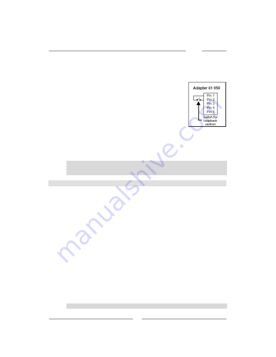
In order to allow connection and use of a loop-
back controller or half-automatic loopback con-
troller, the Power2 provides an input which can 
toggle the locomotive driving direction (track 
polarity). When Pin #1 and Pin #2 of the 5-pole 
“Booster” connector of a Power2 are connected 
together, then the Power2 will toggle its output 
polarity. Depending on the status of [f7], this may 
also apply to breaking the connection between 
Pin #1 and Pin #2 – which may be desirable in 
case of some loopback controllers. 

The connection between Pin #1 and Pin #2 may be conveniently done 
using our Adapter 61 050. 

Pin #1 of the Power2 “Booster” connector is the pin which is closer to 
the Power2 “LocoNet” connector. 

Important

  The last Power2 in a chain of Power2’s controlling a layout in analog 

mode 

cannot

 be used to control a loopback section – check also the 

next section 4.7 (“DCC Digital Turnout Booster”). 


4.7 Power2 as DCC Digital Turnout Booster 

It is possible to configure the last Power2 of a chain of Power2’s 
controlling a layout in analog mode to interpret the turnout/signal 
commands issued, through LocoNet, by throttles or other devices (e.g., 
IB-Switch, Switch-Control, etc.) and convert them to digital commands 
for DCC accessory decoders. This allows for analog train operation and 
digital turnout/signal control – even an automatic analog layout 
operation becomes possible, e.g. by using one or more IB-Switch(es) 
and analog-compatible occupancy detection modules (like our 43 300 
and 43 500 modules) along with LocoNet feedback modules (like our 
63 350 modules). 
Obviously, if this option is used, the last Power2 cannot be used for 
driving a section of an analog layout since, indeed, its power output is 
being used for driving the digital turnout decoders. 
A Power2 can be configured to operate as a DCC digital Turnout 
Booster by connecting Pin #1 and Pin #2 of the Power2 “Booster” 
connector (either using a typical PC style “jumper” or using our adapter 
61 050). This connection must be permanent and precede power-up. 
Pin #1 of the Power2 “Booster” connector is the pin which is closer to 
the Power2 “LocoNet” connector. 
A Power2 which has been configured for “ DCC digital Turnout Booster” 
operation can control up to 1024 DCC turnout addresses (turnout 
addresses 1 through 1024). 


Attention

  Only DCC turnout decoders (DCC accessory decoders) are supported. 

Summary of Contents for DAISY

Page 1: ......

Page 2: ...on Stefano Chiti Batelli with kind support by Mr Robert Frowenfeld Copyright Uhlenbrock Elektronik GmbH Bottrop Germany 1st English edition March 2003 All rights reserved Unauthorized reproduction inc...

Page 3: ...Cables 26 1 4 Power 2 LED status 26 1 5 How to connect it 27 2 Booster use 27 3 Digital system use 3 1 How to connect a DAISY throttle 29 3 2 How to connect additional Boosters and LocoNet devices 29...

Page 4: ...same layout Furthermore if all locomotives are of the DCC format it can also be used to control through locomotive address zero an analog locomotive a locomotive not equipped with a digital decoder Tu...

Page 5: ...l etc and convert them to digital commands for DCC accessory decoders This allows for analog train operation and digital turnout signal control 1 2 Memory function As the power to the layout is turned...

Page 6: ...oming from there If necessary one can branch LocoNet as required so as to allow for connection of more devices or throttles This can be done e g using our LocoNet multiple outlet box art Num 62 250 TI...

Page 7: ...meter input during programming 3 Driving direction indicators triangular LEDs 4 Stop layout Power Off On toggle 5 Turnout key for activating turnout mode and for turnout signal ad dress selection 6 Pr...

Page 8: ...e off key turns them on only as long as the off key remains pressed f1 through f4 In drive mode these keys allow controlling special functions F1 through F4 of the currently selected locomotive Pressi...

Page 9: ...ing this locomotive selection process This is how to proceed Press the Locomotive key The display indicates Loco Release the Locomotive key The display indicates the currently selected locomotive addr...

Page 10: ...t each locomotive address which is already stored in an other memory will be shown with all decimal points turned on and the DAISY will not accept any command to memorize that address again TIP DAISY...

Page 11: ...ssing the Locomotive key or abort locomotive address editing by pressing either the Turnout or Prog keys TIP The 1st memory position can be edited however it cannot be erased 2 2 3 How to edit the loc...

Page 12: ...to edit the current format type of a locomotive Press the Locomotive key The display indicates Loco Release the Locomotive key The display will show the currently selected locomotive address e g 7 Ro...

Page 13: ...ry from which a device can read it later This is how to proceed Press and release the Locomotive key The display will show the currently selected locomotive address Press the Off key and keep it press...

Page 14: ...n toggled will be shown as long as the key remains pressed For example the display will show W 2 the first symbol represents the letter W to indicate Weiche the German word for turnout While in turnou...

Page 15: ...DAISY throttle is connected as an add on throttle to a LocoNet Command Station e g an Intellibox This is how to proceed While in turnout mode press the Turnout key The display will display the turnou...

Page 16: ...ion which has been selected last Press the function key as required for the desired programming con figuration option to be shown Rotate the encoder to select the desired CV Register or Special Option...

Page 17: ...he LocoNet connector of the last Power2 Each Power2 drives its own section of the analog layout electric circuit Each throttle connected to the LocoNet connector of the last Power2 can control any Pow...

Page 18: ...rts circuit coupling Speed knob The speed knob can be used for controlling the locomotive speed Turning the speed knob clockwise increases locomotive speed while turning the speed dial counterclockwis...

Page 19: ...off minimum acceleration deceleration delay f1 on f2 off low acceleration deceleration delay f1 off f2 on medium acceleration deceleration delay f1 on f2 on maximum acceleration deceleration delay No...

Page 20: ...e mode to select a different locomotive This is how to proceed Press the Locomotive key The display indicates Loco Release the Locomotive key The display indicates the currently selected electric circ...

Page 21: ...signal Press the Turnout key to switch from drive to turnout mode While in turnout mode you can use the f1 through f4 keys to toggle the status of a turnout or signal The four LEDs above the f1 throu...

Page 22: ...tle can only be used for changing configuration parameters of the DAISY throttle itself This is how to proceed Press the Prog key The display indicates ProG Release the Prog key The display indicates...

Page 23: ...n IB Control This is how to proceed Disconnect all devices from the Intellibox Connect the DAISY throttle with the LocoNet T connector of the Intellibox using a LocoNet cable Connect the Intellibox to...

Page 24: ...der for 28 and 31 speed steps locomotives 0 off 15 maximum dynamic effect 0 15 5 15 0 DAISY System digital does not generate any Motorola signal 1 DAISY System digital always generates a Motorola sign...

Page 25: ...DAISY 25 Power 2...

Page 26: ...t voltage range adjustable 15 V 20 V Max power output current 2 A Max current output for LocoNet devices 300 mA Suggested transformer 16 V 45 VA LocoNet output with Booster signal 1 3 Cables Please us...

Page 27: ...tput voltage can be adjusted in range 15V through 20V by using the small trimmer potentiometer labeled Ausgangsspannung Output Voltage The output voltage is about 15V when the trimmer is rotated fully...

Page 28: ...need to be connected to a DAISY System then they can be connected either to the Booster connector or to the LocoNet connector In the latter case all additional Boosters must be connected directly to t...

Page 29: ...gether using a LocoNet cable we will shortly describe how to do this Every throttle connected to LocoNet can take control of each electric circuit Power2 by using an automatically assigned identificat...

Page 30: ...ed to the analog layout then the best solution is to add the new Power2 at the end of the existing daisy chain of Power2 s as this will not modify the automati cally assigned identification numbers of...

Page 31: ...ing it this way it is possible to select the FRED number by using the f1 through f4 keys This number will determine which group of 4 Power2 s that FRED will be able to select FRED ID 1 electric circui...

Page 32: ...een completed by pressing the function key in the target electric circuit before that another coupling process can be started once the locomotive has moved within the target electric circuit layout se...

Page 33: ...Power2 s controlling a layout in analog mode to interpret the turnout signal commands issued through LocoNet by throttles or other devices e g IB Switch Switch Control etc and convert them to digital...

Page 34: ...minimum delay means that a locomotive will react very quickly to speed changes f3 switching speed i e half speed f3 off normal speed f3 on switching speed half of normal speed f4 enable disable accele...

Reviews: