


) Set the CV55 and 56 to zero
) Set the CV54 so that the locomotive starts straight at speed 2
) Enlarge the CV55 so that the locomotive moves quickly from speed 0 to 1 and moves as desired at speed 1. The increment
of the change should be 1.
) Compensate restless behavior when changing the speed steps with the CV56. The increment of the change should be 1.
) If necessary, adjust CV2, 5, 6 and start again from step 3.).
If a satisfactory result is not achieved, it may be necessary.
a) The period of the regulation in CV53 are changed.
b) The measuring gap for the EMF voltage in CV58 can be increased (For some motors, quiet operation at low speeds can
only be achieved by this)
c) The slider Offset be changed.
Perform the respective changes in small increments and adjust the PID controller if necessary.
Motorola
In order to achieve the functions F1 - F12 when used with Motorola control panels (eg 6021), the decoder has 3 Motorola
addresses, which are trinär stored in CV47-49. These 3 addresses are also used for decoding. If an address is programmed
decimal under CV1, the decoder up to address 79 automatically stores the trinary equivalent in CV47. For example, to use
Motorola loco addresses up to 255, the CVs 47 - 49 must be programmed directly decimal via Motorola programming (eg
6021 or Intellibox)
On the DCC programming track these CVs can be read, but not programmed.
If the CV47 is programmed by Motorola, the CV1 is not changed and therefore the DCC data format in CV12 is switched off so
that the decoder can not be accidentally accessed via 2 addresses.
If the bit5 is set in the CV29 (DCC long address), the Motorola data format is turned off except for the Motorola programming,
so that the decoder can not react to 2 addresses.
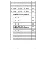
Konfigurations-CVs
In addition to the decoder address, the configuration CVs of a locomotive decoder are certainly the most important CVs.
These are in the In-telliDrive 2 decoder the CVs 29, 50 and 51. A configuration CV usually contains various settings of a
decoder, which are displayed in a maximum of 8 bits (0 - 7). The input value of a CV is calculated from the respective CV
table by adding the values of the desired functions.
Below you can see the meaning and content of the configuration CVs, as well as an example calculation of the value:
Bit
Konfiguration CV 29
Wert
0
Normal direction of travel
0
Opposite direction of travel
1
1
14 / 27 speed steps
0
28 / 128 speed steps
2
2
only digital operation
0
automatic analog/digital switching
4
3
RailCom from
0
RailCom a
8
4
Speed steps via CV 2, CV 5, and CV 6
0
Use characteristic curve from CV 67-
94
16
5
Kurze Adresse (CV 1, Register 1)
0
Long address (CV 17 and 18)
32
Bit
Konfiguration CV 50
Wert
0
Do not use Motorola 2nd address
0
Motorola 2nd address use
1
1
Do not use Motorola 3rd address
0
Motorola 3rd address use
2
2
Do not replace light outputs
0
Replace light outputs
4
3
Frequency light, A1 and A2 = 156Hz
0
Frequency light, A1 and A2 = 24KHz
8
4
SUSI = SUSI
0
SUSI = A3/A4 Logikpegel
16
Example calculation (CV 29)
Normal direction of travel
Wert = 0
28 speed steps
Wert = 2
automatic analog/digital switching
Wert = 4
RailCom off/on
Wert = 8
Speed steps via CV 2, 5, 6
Wert = 0
Kurze Adresse
Wert = 0
The sum of all values is 14.
This value is stored as default in CV 29.
Bit
Konfiguration CV 51
Wert
0
Motor control from
0
Motor control a
1
1
Motor control PID - Controller
0
Motor control SX - controller
2
2
no dynamic period duration
0
dynamic period duration
4
7
Light, A1/A2 PluX (73145)
0
Light, A1/A2 cable/NEM (not 73145)
32
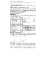
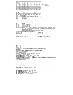
Driving stage characteristic curve
The decoder is preset to a simple, three-point characteristic curve, which determines the minimum, medium and highest
speed. However, it can also be converted to the extended driving step characteristic for 28 speed steps (CV29, Bit4 = 1). This
characteristic curve offers the possibility to set a speed for each of the 28 speed levels. The settings are entered in CVs 67 to
94, whereby a CV is reserved for each of the speed steps 1 - 28.
%
three point
characteristic curve
%
extended
characteristic curve
100
CV5
100
CV94
75
75
50
50
25
CV6
25
CV81
10
CV2
10
CV67
1
7
14
21
28 FS
1
7
14
21
28 FS
RailCom
®
, RailCom Plus
®
The basis of the RailCom®
technology
developed by LENZ®
is
the transmission of data from the decoder to the specially prepared
(CutOut) DCC digital signal on the track. Detectors must be located on the track, which evaluate these decoder data and, if
necessary, forward them to the control center. The decoder transmits, depending on the setting, the decoder address and,
when reading via the main track programming, CV values, which can be displayed by the digital control center (depending on
the detector and control center). In the decoder, the CV29 RailCom® can be switched on
or
off via
bit
3. Further RailCom®
settings
can be
made
in CV 28
. There, for example, RailCom
Plus® is also
switched on via bit
7. If RailCom Plus® is
switched on, the decoder
automatically logs on to a RailCom Plus® capable control centre (e.g., PIKO SmartControl) with its locomotive symbol,
decoder name and special radio symbols within a few seconds. This RailCom Plus® technology means that no locomotive
data has to be stored in the control centre and no locomotive addresses have to be programmed into the decoders.


