background image


S9502-16SMT Hardware Installation Guide | 16 


AC Version 


1.


Ensure there is enough power to supply the system. 
The maximum system power consumption is 54 watts with an input voltage of 100~240V and 
0.7 amperes. 

2.


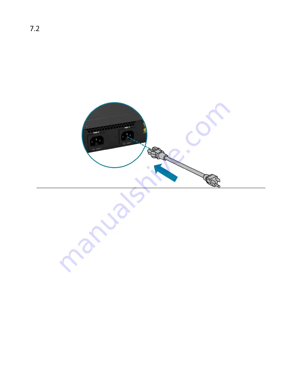
Attach the power cable. 
Plug the power cord into the AC PSU and secure it tightly. 

3.


Verify that the power supply is operating. 
If connected correctly, when turned on, the system LED will light up with a Green color 
designating normal operation. 


Figure 22. 


Summary of Contents for S9502-16SMT

Page 1: ...Hardware Installation Guide S9502 16SMT Disaggregated Cell Site Gateway R1 0 ...

Page 2: ...9502 16SMT AC Version Overview 8 DC Version PSU Overview 9 AC Version PSU Overview 9 Port Overview 9 5 Rack Mounting 11 6 Grounding the Router 13 7 Connecting Power 15 DC Version 15 AC Version 16 8 Verifying System Operation 17 Front Panel LED 17 Management port LED 18 9 Initial System Setup 19 10 Cable Connections 20 Connecting the USB Extender Cable 20 Connecting a Cable to the ToD Interface 20 ...

Page 3: ...tructure to lower costs and rapidly scale existing services for edge computing mobile backhaul and broadband access applications The S9502 16SMT has a lightweight design without fans and fixed power supplies to reduce moving parts and enable longer lasting operations with minimal maintenance servicing It has a powerful dual core processor 100M 1G 10GE high speed interfaces and timing features supp...

Page 4: ...14 AWG wire with ring terminal for DC power supply 6 AWG green and yellow ground wire Wire stripping tools for stripping 6 AWG copper wire PC with terminal emulation software Refer to the Initial System Setup section for details Baud rate 115200 bps Data bits 8 Parity None Stop bits 1 Flow control None ...

Page 5: ... and shipped with a rack mount brackets suitable for 19 inch 48 3cm wide racks The rack mount brackets can be installed at the front or in the center of the S9502 16SMT The depth of the S9502 16SMT chassis is 9 84 inches 25cm The connectors for the power supplies and interfaces will extend outwards from the front panel by 0 55 inches 1 4cm To allow adequate airflow and space for cable connections ...

Page 6: ...C version 100 240V 2 1 ampere Installation spacing and weight load requirement S9502 16SMT is 1RU 1 71 4 35cm in height 17 32 44 0cm in width and 9 84 25 0cm in depth without considering cable routing Thermal requirement S9502 16SMT working temperature is 40 to 65 C 40 F to 149 F airflow direction is front to back and back to front Installation tools required 2 Philips Screwdriver 6 AWG wire strip...

Page 7: ...Lock Washers 1 set 0 008lbs 3 8g set 3 Rack Mount Bracket 1 98 x 1 69 x 0 79 19 width rack 50 4 x 43 x 20mm 2 pcs 0 15lbs 67 2g 2 pcs 0 07lbs 33 6g pcs 4 Screw Kit for Rack Mount Bracket 8 x Screws M4 0 L6 5mm 1 set 0 01lbs 6 5g set 5 Cable USB2 0 A TYPE Male to Female 200mm 7 87 200mm 1 pcs 0 021lbs 9 7g pcs 6 AC power cord AC version only 72 05 1830mm 2 pcs 1 04lbs 470g 2 pcs 0 52lbs 235g pcs 7 ...

Page 8: ...rsion 9 52lbs 4 32kg DC Version 9 21lbs 4 18kg Ground lug 0 022lbs 10g Rack mount bracket 0 07lbs 33 6g AC Power AC version only 0 52lbs 235g per pcs USB extension cord 0 021lbs 9 7g RJ45 to DB9 Female Cable 0 27lbs 123 9g per pcs Screw kit for ground lug 0 008lbs 3 8g per set Screw kit for rack mount bracket 0 01lbs 6 5g per set Dimension S9502 16SMT W x D x H 17 32 x 9 84 x 1 713 440 x 250 x 43 ...

Page 9: ...S9502 16SMT Hardware Installation Guide 7 4 Identifying Your System S9502 16SMT DC Version Overview Figure 5 Figure 6 ...

Page 10: ...S9502 16SMT Hardware Installation Guide 8 S9502 16SMT AC Version Overview Figure 7 Figure 8 ...

Page 11: ...ower supply unit PSU Figure 9 AC Version PSU Overview 1 1 Fixed power supply unit PSU Figure 10 Port Overview Port ID Form Factor Maximum Support Distance Support Speed 0 3 RJ45 238 01ft 100m 100M 1GE 4 11 SFP 24 85mi 40km 1GE 12 15 SFP 24 85mi 40km 1GE 10GE DC Version Figure 11 ...

Page 12: ...S9502 16SMT Hardware Installation Guide 10 AC Version Figure 12 ...

Page 13: ...les provided on the both sides of the case and secure the brackets using the 8 M4 0 L6 5mm screws provided with the package Figure 13 2 Secure the router onto the rack posts Mark the location on both posts to ensure it is leveled before securing the router onto the rack using the screws and cage nuts provided with the package See Figure 14 For rack post widths wider than 19 different brackets are ...

Page 14: ...S9502 16SMT Hardware Installation Guide 12 Figure 15 ...

Page 15: ...onductor or operate the equipment without correctly grounding the equipment If there is any uncertainty about the integrity of the equipment s grounding please contact the electrical inspection authority or a certified electrician 1 Before grounding the router ensure that the rack is properly grounded and in compliance with local regulatory guidelines Ensure that there is nothing that can obstruct...

Page 16: ...ed location for securing the grounding lug which is located on the side of the router 6 Using 2 M4 screws and 4 washers provided with the package contents firmly lock the grounding lug to the designated grounding location on the router Figure 17 Figure 18 Figure 19 ...

Page 17: ... the specified torque Tighten the screws to a torque value of 6 94lbf in 10 If the torque is not enough the lug will not be secure and may cause malfunctions If the torque is too much the terminal block or lug may be damaged Figure 21 4 Feed DC power into the system The PSU will immediately output 12V and 5VSB to the system when a 48V DC power source is applied The PSU has a built in 6 amperes fas...

Page 18: ...wer consumption is 54 watts with an input voltage of 100 240V and 0 7 amperes 2 Attach the power cable Plug the power cord into the AC PSU and secure it tightly 3 Verify that the power supply is operating If connected correctly when turned on the system LED will light up with a Green color designating normal operation Figure 22 ...

Page 19: ...Solid Green All PSU work well Blinking Yellow One or more PSU s fail SYNC Off System timing synchronization is disabled or in free run mode Note need NOS to activate this feature Solid Green System timing core 1588 and SyncE is synchronized to external timing source ex GNSS 1PPS PTP BITS etc Note need NOS to activate this feature Blinking Green System is synchronized in SyncE mode Note need NOS to...

Page 20: ...gement port LED Left LED Condition Equipment Status Off No link Green solid Link up at 1G Green blinking TX RX activity at 1G Right LED Condition Equipment Status Off No link Amber solid Link up at 10M 100M Amber blinking TX RX activity at 10M 100M ...

Page 21: ...a RJ45 serial cable into the console port and connect the other end to the computer Cable types may vary depending on the model Figure 24 2 Check for serial control availability Disable any serial communication programs running on the computer such as synchronization programs to prevent interference 3 Launch a terminal emulator Open a terminal emulator application such as HyperTerminal Windows PC ...

Page 22: ...B port female connector located on the front panel of the router The USB port is a maintenance port Figure 25 Connecting a Cable to the ToD Interface 1 Connect one end of a straight through Ethernet cable to the GNSS unit 2 Connect the other end of the straight through Ethernet cable to the port marked TOD located on the front panel of the router Figure 26 ...

Page 23: ...ightening and damaging the optic fibers it is not recommended to use tie wraps with optical cables Read the following guidelines before connecting the transceiver Before installing the router take into consideration rack space requirements for cable management and plan accordingly It is recommended to use hook and loop style straps to secure and organize the cables For easier management label each...

Page 24: ...ounded such as by wearing an ESD wrist strap Please follow the steps below for connecting a transceiver 1 Remove the new transceiver from its protective packaging 2 Remove the protective plug from the transceiver port 3 Place the bail wire handle in the unlocked position and align the transceiver with the port 4 Slide the transceiver into the port and use gentle pressure to secure it in place An a...

Page 25: ...mpromising stability Otherwise personal injury and or equipment damage may result Caution Use of controls or adjustments or performance of procedures other than those specified herein may result in hazardous radiation exposure Warning Do not use optical instruments to view the laser output The use of optical instruments to view laser output increases eye hazard Use only UL CSA IEC EN60825 1 2 reco...

Page 26: ...ice personnel or users familiar with restrictions applied to the location reasons therefore and any precautions required Only afforded by the use of a tool or lock and key or other means of security and controlled by the authority responsible for the location Suitable for installation in Information Technology Rooms in accordance with Article 645 of the National Electrical Code and NFPA 75 ...

Page 27: ...www ufispace com www ufispace com ...

Reviews: