background image


S9180-32X Hardware Installation Guide | 1 


1


Overview 


The UfiSpace S9180-32X is a high-performance, versatile open networking white box switch 
that is designed to address the fast growing segment of the Ethernet switching market and 
the needs to push capacity to the next level.  

 
With 32 x 100G QSFP28 ports, the S9180-32X switch is where computer resources (servers 
or blade chassis) are centralized and managed in a structured way utilizing high-efficiency 
Ethernet connectivity. 
 
With advanced capabilities, these switches deliver performance and intelligence to the 
network edge in a flexible 1RU form factor that helps reduce infrastructure and 
administrative costs.  

The S9180-32X is the epitome of future networking with a powerful 4-core/8-core processor 
and 32 high-speed 100G interfaces. It comes with redundant, hot swappable components 
for convenience, increased availability, reliability  and lower costs of maintenance. 


This document describes the hardware installation process for S9180-32X. 


Summary of Contents for S9180-32X

Page 1: ...Hardware Installation Guide S9180 32X 100G Data Center Switch R1 1 ...

Page 2: ...rview 7 DC Version PSU Overview 8 AC Version PSU Overview 9 Fan Overview 10 Port Overview 10 5 Rack Mounting 11 6 Installing Fan Modules 12 7 Installing Power Supply Units 13 8 Grounding the Switch 15 9 Connecting Power 16 DC Version 16 AC Version 17 10 Verifying System Operation 18 Front Panel LED 18 PSU FRU LED 18 Fan FRU LED 19 11 Initial System Setup 20 12 Cable Connections 21 Connecting the U...

Page 3: ...and managed in a structured way utilizing high efficiency Ethernet connectivity With advanced capabilities these switches deliver performance and intelligence to the network edge in a flexible 1RU form factor that helps reduce infrastructure and administrative costs The S9180 32X is the epitome of future networking with a powerful 4 core 8 core processor and 32 high speed 100G interfaces It comes ...

Page 4: ...18 AWG wire with ring terminal for grounding PC with terminal emulation software Refer to the Initial System Setup section for details Baud rate 115200 bps Data bits 8 Parity None Stop bits 1 Flow control None Illustrations are for reference purposes only Actual equipment and scenarios may differ ...

Page 5: ... S9180 32X width is 17 32 inches 44 0cm and shipped with a rack mount brackets suitable for 19 inch 43 8cm wide racks The depth of the S9180 32X chassis is 16 9 inches 42 8cm without the field replaceable units FRUs and comes with adjustable mounting rails suitable for rack depths of 24 inches 60 9cm to 31 inches 78 7cm The handle for the fan units will extend outwards by 1 inch 2 5cm and the hand...

Page 6: ... Task Check Date Power voltage and electric current requirement DC version 40 to 72V DC 16A maximum x2 or AC version 100 to 240V 7A maximum x2 Installation spacing requirement S9180 32X spacing requires a height of 1RU 1 72 4 5cm a width of 19 48cm and a depth of 16 9 inches 42 8cm Thermal requirement S9180 32X s working temperature is 0 C to 45 C 32 F to 113 F Installation tools required 2 Philli...

Page 7: ...sts 2 x Mounting Rail Inner 9 9 x 1 42 x 0 08 251 5 x 36 x 2mm for 24 to 31 rack depth 2 pcs 0 617lb 280g 2 pcs 0 308lb 140g pcs 4 2 Adjustable Mounting Rail for 4 posts 2 x Mounting Rail Outer 12 34 x 1 69 x 0 74 313 5 x 43 x 19mm for 24 to 31 rack depth 2 pcs 0 70lb 318g 2 pcs 0 35lb 159g pcs 5 Screw Kit for Adjustable Mounting Rail 8 x Screws M4 0 L6 5mm 1 set 0 02lb 7g set 6 Power Cord AC Vers...

Page 8: ...C PSU 2 2lbs 1 0kg AC PSU 2 6lbs 1 2kg Fan module 0 41lbs 185g Adjustable mounting rail 0 66lbs 299g DC power cord DC version only 1 36lbs 617g AC power cord AC version only 0 51lbs 235g RJ45 to DB9 female cable 0 23lbs 105g Dimension S9180 32X W x D x H 17 32 x 16 88 x 1 73 440 x 428 8 x 44mm PSU W x D x H 2 89 x 7 28 x 1 57 73 5 x 185 x 40mm Fan module W x D x H 2 18 x 4 09 x 1 59 55 6 x 10³ 9 x...

Page 9: ...S9180 32X Hardware Installation Guide 7 4 Identifying Your System S9180 32X System Overview Figure 5 ...

Page 10: ...irflow identified with a blue latch The picture on the right is the DC PSU for front to back airflow identified with a red latch Back to Front Airflow PSU Front to Back Airflow PSU Figure 6 The DC power supply units are the same size for both back to front airflow and front to back airflow Therefore only the dimensions for front to back airflow PSU will be provided in the figure below Front to Bac...

Page 11: ...irflow identified with a blue latch The picture on the right is the AC PSU for front to back airflow identified with a red latch Back to Front Airflow PSU Front to Back Airflow PSU Figure 8 The AC power supply units are the same size for both back to front airflow and front to back airflow Therefore only the dimensions for front to back airflow PSU will be provided in the figure below Front to Bac...

Page 12: ...p picture is for fans with back to front airflow identified with a I The picture on the bottom is for the fans with front to back airflow identified with a E Back to Front Airflow Fans Front to Back Airflow Fans Figure 10 Port Overview Port ID Form Factor Maximum Support Distance Support Speed 1 32 QSFP28 6 21mi 10km 40 100G 33 34 SFP 6 21mi 10km 1 10G Figure 11 ...

Page 13: ... rack mount brackets onto the switch Align the rack mount brackets with the holes provided on the both sides of the case and secure the brackets using the 8 M4 0 L6 5mm screws provided with the package Figure 12 2 Secure the switch onto the rack posts Mark the location on both posts to ensure it is leveled before securing the switch onto the rack Figure 13 For a 4 post rack first secure the adjust...

Page 14: ...s come pre installed and the following steps are instructions on how to install a new fan module 1 Loosen the captive screw located on the fan module Figure 15 2 Grip the fan s handle and firmly pull it out of the fan bay Figure 16 3 Align the new fan module with the fan bay 4 Carefully slide the new fan module into the fan bay and gently push until it is flush with the case 5 Secure the captive s...

Page 15: ...s are the same for all models DC AC Figure 18 Shock hazard For safety please disconnect all power inputs from the power supply unit before servicing the switch 1 Locate the release tab on the PSU Then press and hold down the release tab to unlock the PSU from the power bay 2 While holding down the release tab grip the PSU s handle and firmly pull it out of the power bay DC Version AC Version Figur...

Page 16: ... An audible click will be heard when the PSU is installed correctly The PSU will not go in all the way if it is in the wrong direction Illustrations are for reference purposes only Actual PSU position may differ DC Version AC Version Figure 20 ...

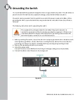
Page 17: ...eat the ground conductor or operate the equipment without correctly grounding the equipment If there is any uncertainty about the integrity of the equipment s grounding please contact the electrical inspection authority or a certified electrician 1 Before grounding the switch ensure that the rack is properly grounded and in compliance with local regulatory guidelines Ensure that there is nothing t...

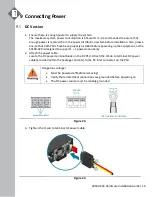
Page 18: ...rly installed before powering up the equipment as the S9180 32X is designed to support 1 1 power redundancy 2 Attach the power cable Locate the DC power terminal block on the DC PSU Attach the D Sub to terminal DC power cable provided within the package contents to the DC inlet connector on the PSU Dangerous voltage Must be powered off before removing Verify that all electrical connections are gro...

Page 19: ...he switch is operating normally AC Version 1 Ensure there is enough power to supply the system The maximum system power consumption is 451 watts with an input voltage of 100 240V AC It is recommended to ensure that enough power is reserved from the power distribution system before installation Also please ensure that both PSUs have been properly installed before powering up the equipment as the S9...

Page 20: ...ber Power is up but Host CPU BMC boot failed FAN Off Fans are not initialized Solid Green All Fans are work normal Solid Amber Fan fail one or more Fans need service PS1 Off No power Solid Green PSU0 working normal Solid Amber PSU0 fail PSU0 needs service PS2 Off No power Solid Green PSU1 working normal Solid Amber PSU1 fail PSU1 needs service PSU FRU LED Additional information about PSU status ca...

Page 21: ...voltage fan failure and or over temperature Blinking Red 1 sec Input power cord unplugged or input power lost with a second power supply in parallel still with AC input power Blinking between Green and Red Power supply warning events where the power supply continues to operate high temp high power high current and or slow fan Fan FRU LED LED Condition Equipment Status Off No input power Solid Gree...

Page 22: ... RJ45 serial cable into the console port and connect the other end to the computer Cable types may vary depending on the model Figure 27 2 Check for serial control availability Disable any serial communication programs running on the computer such as synchronization programs to prevent interference 3 Launch a terminal emulator Open a terminal emulator application such as HyperTerminal Windows PC P...

Page 23: ...ent label each fiber optic cable and record its respective connection Maintain a clear line of sight to the port LEDs by routing the cables away from the LEDs Before connecting anything cables transceivers etc to the switch please ensure to discharge any static electricity that may have built up during handling It is also recommended the cabling be done by a professional who is grounded such as by...

Page 24: ...t compromising stability Otherwise personal injury and or equipment damage may result Caution Use of controls or adjustments or performance of procedures other than those specified herein may result in hazardous radiation exposure Caution Only Laser Class 1 optical transceivers shall be used Warning Do not use optical instruments to view the laser output The use of optical instruments to view lase...

Page 25: ...www ufispace com www ufispace com ...

Reviews: