


8
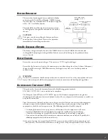
Use the “
s
“UP or “
t
“DOWN buttons to scroll through the MAIN MENU or OPTIONS. Press “SEND” to select displayed
screen choice. NOTE: Rotate the selector off menu at any time to EXIT. Selections will NOT be saved unless you press “SEND”
PRESS “
s
“UP to scroll through menu items in this order.
press “
s
“
press “
s
“
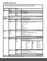
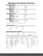
MAIN MENU
SUB MENU
OPTIONS Notes
SETUP
SET TIME
Use to set current time.
SET DATE
Use to set current date.
C < - - -> F
˚F or ˚C
Use to select temperature scale.
LANGUAGE
ENGLISH
Use to select language.
FRENCH
SPANISH
EXIT
Return to main menu.
GAS ZERO
RESET GAS ZERO
Press “SEND” to start.
(EagleX ONLY)
Automatically returns to main menu.
PRESSURE
SMOOTH
ON/OFF
Use to change screen update rate.
RESOLVE
HIGH
Use to select display resolution.
LOW
PS UNITS
Use to select desired unit of measure. Choose beetween:
In H2O
inches H2O (water gauge)
mbar millibar
mmH2O
millimeters of H2O
Pa Pascals
kPa Kilopascals
PSI
Pounds per square inch
mmHg
Millimeters of mercury
hPa
Hecto pascals
EXIT
Return to main menu.
REPORT
COMB’N
VIEW
When viewing reports:
PRESSURE
DEL ALL
-Press “
s
“UP or “
t
“DOWN to select report #.
EXCH
-Press and hold “
s
“UP or “
t
“DOWN to change the displayed
TEMP
lines in VIEW.
ROOM CO
-Press SEND to print current viewed report.
-Press and hold SEND to exit view.
EXIT
Return to Sub Menu.
EXIT
Return to main menu.
SCREEN
CONTRAST
00~20
Use to change screen contrast.
AUX
LINE 1
-Select parameter displayed for each line.
LINE 2
-Press “
s
“UP to choose between:
LINE 3
∆
T
Temp differential
TIME
(shows time)
LINE 4
CO
Carbon Monoxide
DATE
(shows date)
P
Pressure
Losses
X
Excess Air
R
CO/CO2 Ratio
Efn
Efficiency
CO2
Carbon Dioxide
NO NO
O2 Oxygen
COa
CO Air Free
TI
Inlet Temp (T1)
BAT
Battery Level
TF
Flue Temp (T2)
D Draft
EXIT
Return to Sub Menu.
HEADER
HEADER1
Customize header information
HEADER2
Screen shows (*OUR COMPANY NAME &_ _ _ _)
-Press UP or DOWN to scroll through letters and symbols to
choose, press ENTER.
EXIT
Return to Sub Menu.
EXIT
Return to main menu.
SERVICE
Used by technicians to calibrate combustion gas sensors.
m
Ain
m
EnU
n
AviGAtiOn


