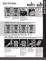
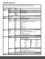
UEi Eagle Owner'S Manual Download Page 3

3

D

ispLAy

 p

ArAmEtErs

 O

n

 UE

i

 C

OmbUstiOn

 A

nALyzErs


• 

TF

 = 

Flue Temperature

: Calculate net temperature in °F or °C.  


       -  Shows ambient temp after fresh air calibration and ‘

- O C -

’ when probe is disconnected.


T

 = 

Net Temperature

:   


    - Differential of flue temperature minus ambient (or inlet) temperature


    - Differential of  T1 - T2


• 

T∆ 

Temperature Differential

:


• 

O2

 = 

Oxygen

: O2 percentage displayed


• 

CO

 = 

Carbon Monoxide

: CO ppm (parts per million) displayed. 


    - ‘

- - - -

’ or ‘

- OC -

’  is displayed if there is a fault with the CO sensor or  


      the instrument has not been zeroed correctly, switch off instrument and try again.


• 

CO2

 = 

Carbon Dioxide:


    -  EAGLE (C125 & C127) Calculated from the fuel selected and the measured O2 level


    -   EAGLE (C125 & C127) Will display ‘

- - - -

’ or ‘

-O>-

’ if the O2 level is too    


      high to calculate CO2 or in fresh air.


    -  Calculated value is only displayed during the combustion test.


    -  EAGLE X (C155 & C157) Direct measurement CO2 ppm (parts per million) displayed.


• 

X

 = 

Excess Air:


    - Indicated as ‘

XAIR %

’ on the printout


    - A calculated percentage of O2 above the theoretical level required for complete combustion.


    - 

Is required to completely burn the fuel due to poor mixing and assisting in venting flue gases 


    - 

Only displays a reading during combustion test. 


    - ‘

- - - -

’ or ‘

-O>-

’ is displayed in fresh air.


• 

EFF

 = 

Efficiency

:  


    - Calculated based on gas readings, net temperature and fuel selected.


    - Value is combustion efficiency, not appliance efficiency.


• 

∆ 

Loss


    - Total losses calculated from Combustion Theory. A summation of the next three parameters


      • Dry %: Calculated heat lost turning the Carbon in the fuel to Carbon Dioxide (CO2)


      • Wet %: Calculated heat lost turning the Hydrogen in the fuel into water (H2O)


      • CO Loss %: Calculated loss due to partially burnt Carbon.  


      Any CO in the flue has the potential to be turned into CO2 releasing and losing more  


      heat up the flue.


• 

CO a 

Carbon Monoxide Air-Free

: Referenced to an oxygen level of 0%. 


    -

  Do not confuse this reading with the actual CO reading

 as detailed above.  


    -  See the Combustion Efficiency Calculation sections for more details. 


• 

AMB

 = 

Air Inlet

:


    -  Temperature used to calculate the NET temperature. 


• 

CO/CO2

 = 

CO/CO2 Ratio

: The ratio of measured CO divided by CO2.


    - It gives an indication of:


      • How good a gas sample the instrument is reading.


      • How clean the boiler is running.


    - Example: A new or clean domestic boiler will display a ratio of less than 0.004, a unit in need 


        of cleaning 0.004 - 0.008 and a unit needing a major overhaul will show at least 0.008.


    - Only displays a reading during combustion test. ‘

- - - -

’ is displayed while in fresh air.


• 

D

 = 

Draft Pressure


• 

P

 = 

Pressure


• 

NO

 = 

Nitric Oxide

:


• 

-PO-

 = 

Pump Off


    -  Measured gases will display this when pump is off. 


• 

-O>-

 = 

High O2 level

:


    -  Calculated values will display this when O2 levels are greater than 18%


    -   Values are calculated with fuel choice and the O2 readings


• 

-OC-

 = 

Probe Not Connected

:


    -  Temperature values will display this when the probe is not connected or is open


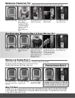
    -  Press and hold the “PUMP” button to Zero the pressure sensor in selector positions that display  


      measured or calculated values “Aux” & “Flue Test”. 


• 

N/F 

Not Found

:


    -  Displayed when not available or not installed ie: NO on a C155 or C125.

NOTE: See page 8 for complete auxiliary display listings.

Summary of Contents for Eagle

Page 1: ...1 Eagle Eagle X Owners Manual ...

Page 2: ...r Charge Indicator Light 4 Line Backlit Display Display Line Lights Particle Filter Inside Water Trap Water Trap Protective Rubber Boot w built in Magnets Flue Probe Temperature Plug Plugs into T1 Narrow Pin MUST be on the Right hand side Flue Probe Gas Inlet Plug Temperature Connections Flue Probe Temp T1 Inlet Temp T2 Pressure Connections Single Input Draft P1 Differential Input Testing Pressure...

Page 3: ...culated heat lost turning the Carbon in the fuel to Carbon Dioxide CO2 Wet Calculated heat lost turning the Hydrogen in the fuel into water H2O CO Loss Calculated loss due to partially burnt Carbon Any CO in the flue has the potential to be turned into CO2 releasing and losing more heat up the flue CO a Carbon Monoxide Air Free Referenced to an oxygen level of 0 Do not confuse this reading with th...

Page 4: ... as soon as possible Use the GAS ZERO function Eagle X only to purge the analyzer of excess gases To do this on a standard Eagle remove the probe from the flue and turn ON the pump Always allow the readings to return to zero 20 9 for O2 prior to shutting the unit off The meter will not switch off until the CO reading is below 20 ppm WARNING The probe will be hot from flue gases Remove the probe fr...

Page 5: ...ing testing Connect flue probe thermocouple connector to T1 and connect flue probe to water trap as shown above Use optional probe with T2 for inlet temperature Insert Flue Probe in stack Adjust the cone so the end of the probe is approxi mately at the center of the stack 4 stack adjust cone to aprox 2 from end of probe Gas Zero EagleX series only Rotate test selector to Menu Make sure Analyzer is...

Page 6: ...draft probe for measuring pressure Press and hold t DOWN button to zero pressure sensor Rotate test selector to Temp Connect flue probe thermocouple or accessory thermocouple connector to T1 Connect accessory thermocouple probe to T2 Compatible with any K Type thermocouple probe or clamp Place thermocouples in test locations to start testing Observe T1 T2 and Differential delta T Press SEND to pri...

Page 7: ...ess Air O2 and CO readings both before and after the blower turns on If the heat exchanger is sealed your O2 and CO readings should remain fairly stable A breach in the heat exchanger may allow fresh air to be forced into the flue after the blower turns on due to a pressure increase in the plenum The result may be a rise in the measured O2 in the stack gas and an increase in the Excess Air In some...

Page 8: ... inch mmHg Millimeters of mercury hPa Hecto pascals EXIT Return to main menu REPORT COMB N VIEW When viewing reports PRESSURE DEL ALL Press s UP or t DOWN to select report EXCH Press and hold s UP or t DOWN to change the displayed TEMP lines in VIEW ROOM CO Press SEND to print current viewed report Press and hold SEND to exit view EXIT Return to Sub Menu EXIT Return to main menu SCREEN CONTRAST 00...

Page 9: ...s 04 to 06wc Overfire Draft Water Column Inches 02wc Carbon Monoxide parts per million 100ppm Smoke 0 or manufacturer s recommendation Positive Overfire Gas Oil Oxygen 3 to 9 O2 Stack Draft Water Column Inches 02 to 04wc Overfire Draft Water Column Inches 0 4 to 0 6wc Carbon Monoxide parts per million 100ppm NOTE Follow manufacture guidelines for the specific equipment being serviced Typical Exces...

Page 10: ... Verify proper combustion O2 CO Stack Temp Efficiency Hi Low fire Gas Pressure Send and Return Water temp 80 Furnace Verify proper combustion O2 CO Stack Temp Vent Pressure Efficiency Verify Set Up Gas Pressure Test Limit Switch Pressure Switch Verify proper operation Static Duct Pressure Temperature Rise AC side Static Pressure Drop across coils 90 Furnace Verify proper combustion O2 CO Stack Tem...

Page 11: ...emperature Rise AC side Static Pressure Drop across coils Oil Furnace Verify proper combustion O2 CO Stack Temp Stack Draft Efficiency Test Verify Smoke Set Up Over Fire Draft Verify proper Static Duct Pressure Temperature Rise AC side Static Pressure Drop across coils Atmospheric Furnace Draft Verify proper Temperature Rise AC side Static Pressure Drop across coils Verify proper combustion O2 CO ...

Page 12: ...nce between the ambient pressure level and the pressure level in the flue This is created either by the natural buoyancy of the hot gases created in combustion lifting or by an inducer fan that assists the flow of flue gases up the stack Most combustion equipment will specify the amount of draft that is required for proper operation Draft helps draw combustion air into the combustion chamber and a...

Page 13: ... product of combustion and from wet fuel is recovered and the wet loss term is zero Gross efficiency calculations assume that the energy contained in the water vapor is not recovered Since the fuel air mixture is never consistent there is the possibility of unburned partially unburned fuel passing through the flue This is represented by the unburned carbon loss Losses due to combustible matter in ...

Page 14: ...lvents or strong detergents as they may damage the finish impair safety or effect the reliability of the structural components Emptying Cleaning the In Line Water Trap The in line water trap should be checked and emptied on a regular basis Water vapor will condense in the probe line which may cause the water trap to fill suddenly if the probe is moved Care should be taken at all times Carefully re...

Page 15: ...lations Electromagnetic Compatibility EMC This product has been tested for compliance with the following generic standards EN 50081 1 EN 50082 1 and is certified to be compliant The European Council Directive 89 336 EEC requires that electronic equipment does not generate electromagnetic disturbances that exceed defined levels and has an adequate level of immunity to enable it to be operated as in...

Page 16: ... rights You may also have other rights which vary from state to state U S A 1 8 0 0 5 4 7 5 7 4 0 F a x 5 0 3 6 4 3 6 3 2 2 C A N A D A 1 8 7 7 4 7 5 0 6 4 8 F a x 6 0 4 2 7 8 8 2 9 9 W W W U E i T E S T C O M COPYRIGHT 2013 UEi EAGLE Combustion Analyzers is a trademark of UEi IMAG454 5k 11 13 18323 C125 C127 C155 C157 Temperature Measurement Flue Temp Range 20 2400 F 29 1315 C Inlet Temperature p...

Reviews: