DL479
NCV
°C
°F
CAT IV 600V
CAT III 1000V
MAX
µA
A
CAT Ill
1000V 600A
True RMS
Hz / Duty
MAX/MIN
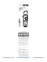
OVERVIEW
S
U
V
W
T
C
D
J
G
K
N
M
P
O
Q
R
A
H
I
L
E
F
B
A. Clamp:
Measure inductive AC current. Opens to 1.25” (31.7mm).
B. Conductor Alignment Marks:
Used to aid the visual alignment of a conductor
when measuring inductive amperage. Greatest accuracy is achieved when the
conductor inside the clamp is centered at the intersection of these marks.
C. Wire Separation Tab/NCV sensor:
Used to isolate an individual wire from a
bundle for testing. NCV sensor detects live voltage.
D. Test Lead Holder:
Used for hand-free use of the test probes.
E. Worklight:
Lights clamp area in dark work environments.
F. Category Max Indicator:
Maximum CAT Rating for Clamp/jaw.
G. Hand Guide:
Used as a point of reference for the operator’s safety.
H. NCV Alert Light:
Indicates voltage when in NCV mode.
I. Clamp Lever:
Opens and closes current clamp jaw. The clamp uses a high-
tension spring to close the jaw. Do not allow fingers or objects to become
pinched in the base as the jaws close.
J. Hold Button
• Press to hold the reading on the display. Press again to return to live reading.
• Press and hold to turn on Worklight and Backlight. Press and hold again to
turn off.
K. Function Dial:
Turns on meter and is used to select the function.
L. Select Button
• Used to choose measurement mode from a single dial selection; AC or DC
volts, Resistance, Continuity, Diode or Capacitance, ˚F or ˚C in temperature mode.
• Press and hold the button while turning the meter on to disable Apo
(auto power off).
M. Max/Min Button
• Press to enter MAX/MIN mode.
• Press repeatedly to alternate between Maximum and Minimum readings.
• Press and hold to return to live readings.
N. Range Button:
• Press repeatedly to cycle through manual ranges.
• Press and hold to return to auto ranging mode.
•
AT is displayed on LCD only during auto ranging mode.
O. Apo:
Auto power off after 30 minutes of use. Press and hold the SELECT button
while turning the meter on to disable Apo (auto power off).
P. Display:
• High contrast display.
Q. Category Max Indicator:
Maximum CAT Rating for input jacks.
R. Input Jacks:
Multifunction and Common jacks.
•
Multifunction input port used for measuring: AC or DC volts, Resistance,
Continuity, Diode, Capacitacne, DC µA and temperature.
•
Use CAT III test leads or higher.
S. Serial Number
T. Magnetic Mount:
For hands-free work.
U. Battery Cover:
Easy access for replacing batteries.
V. Battery Cover Latches:
Convenient, quick opening.
W. Test lead holders:
For storing test leads when not in use.
17211 • 0616
• Backlight
• Worklight
• Audible voltage indicator
• Low battery indicator
• Auto power off
• Test lead storage
• Overmolded grip
• Magnetic mount
• Battery compartment latches
Test Lead Notes
Cat IV and CAT III Measurement Locations
• Ensure the test lead shield is pressed firmly in place. Failure to use the CAT
IV shield increases arc-flash risk.
CAT II Measurement Locations
• CAT IV shields may be removed for CAT II locations. This will allow testing
on recessed conductors such as standard wall outlets. Take care not to lose
the shields.
WARNING:
Test Lead category protections apply only to test leads and
should not be confused with the meter’s specific CAT rating. Observe the
maximum category protection indicated on the meter the test leads are
plugged into.
CAUTION
: If the test leads need to be replaced, you must use a new one
which should meet EN 61010-031 standard, rated CATIII 1000V or better.
4mm
18mm
4mm
18mm
•
When the batteries are too low for safe
operation, the Low Battery indicator will display.
• Rotate latches until Unlock symbols are aligned
with arrows. Remove battery cover.
• Replace the old batteries with 2 new (AAA)
batteries.
• Replace the battery cover.
• Rotate latches until the lock symbols are aligned
with arrows.
Battery Replacement
www.
GlobalTestSupply
.com
Find Quality Products Online at:


