background image

11

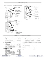
Furnaces (continued): Atmospheric, Gas & Oil

Atmospheric Furnace

Draft

Verify proper


• Temperature Rise


• AC side Static Pressure 


   Drop across coils

Verify proper combustion:


• O2


• CO


• Stack Temp


• Efficiency

WHERE TO TEST (CONT.)

Natural Gas & Propane

Verify proper combustion:


• O2


• CO


• Stack Temp


• Vent Pressure


• Efficiency

Test


• Limit Switch


• Pressure Switch

Set Up


• Gas Pressure

Verify proper:


• Static Duct Pressure


• Temperature Rise


• AC side Static Pressure 


   Drop across coils

Oil Furnace

Verify proper combustion:


• O2


• CO


• Stack Temp


• Stack Draft


• Efficiency

Test & Verify: 


• Smoke

Set Up


• Over Fire Draft

Verify proper


• Static Duct Pressure


• Temperature Rise


• AC side Static Pressure 


   Drop across coils

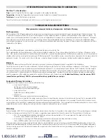
WHAT RESULTS ARE GENERALLY ACCEPTABLE

Atmospheric Gas Fired Burners


• Oxygen   .  .  .  .  .  .  .  .  .  .  .  .  .  .  .  .  .  .  .  .  .  .  .  .  .  .  .  .  .  .  .  .  7 to 9% O2


• Stack Temperature     .  .  .  .  .  .  .  .  .  .  .  .  .  .  .  .  .  .  .  .  . 325 to 500°F


• Draft (Water Column Inches)   .  .  .  .  .  .  .  .  .  .  .  .  - .02 to - .04wc”


• Carbon Monoxide (parts per million)   .  .  .  .  .  .  .  .  .  .  . <100ppm

Gas Fired Power Burners


• Oxygen   .  .  .  .  .  .  .  .  .  .  .  .  .  .  .  .  .  .  .  .  .  .  .  .  .  .  .  .  .  .  .  .  3 to 6% O2


• Stack Temperature     .  .  .  .  .  .  .  .  .  .  .  .  .  .  .  .  .  .  .  .  . 275 to 500°F


• Stack Draft (Water Column Inches)   .  .  .  .  .  .  .  - .02 to - .04wc”


• Overfire Draft (Water Column Inches)   .  .  .  .  .  .  .  .  .  .  .  - .02wc”


• Carbon Monoxide (parts per million)   .  .  .  .  .  .  .  .  .  .  . <100ppm

Oil Fired Burners (#2 Oil Fuel)


• Oxygen   .  .  .  .  .  .  .  .  .  .  .  .  .  .  .  .  .  .  .  .  .  .  .  .  .  .  .  .  .  .  .  .  4 to 7% O2


• Stack Temperature     .  .  .  .  .  .  .  .  .  .  .  .  .  .  .  .  .  .  .  .  . 325 to 600°F


• Stack Draft (Water Column Inches)   .  .  .  .  .  .  .  - .04 to - .06wc”


• Overfire Draft (Water Column Inches)   .  .  .  .  .  .  .  .  .  .  .  - .02wc”


• Carbon Monoxide (parts per million)   .  .  .  .  .  .  .  .  .  .  . <100ppm 


• Smoke    .  .  .  .  .  .  .  .  .  .  0 (or manufacturer’s recommendation)

Positive Overfire Gas & Oil


• Oxygen   .  .  .  .  .  .  .  .  .  .  .  .  .  .  .  .  .  .  .  .  .  .  .  .  .  .  .  .  .  .  .  .  3 to 9% O2


• Stack Draft (Water Column Inches)   .  .  .  .  .  .  .  - .02 to - .04wc”


• Overfire Draft (Water Column Inches)   .  .  .  .  +0 .4 to +0 .6wc”


• Carbon Monoxide (parts per million)   .  .  .  .  .  .  .  .  .  .  . <100ppm 

NOTE: Follow manufacture guidelines for the specific equipment being 

serviced .

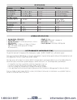
Typical Excess Air Level


O2% (measured) 

Excess Air %

Natural gas 

3% 

16 .7%

Light Oil 

5% 

31%

Coal 8% 62%

www.

.com

[email protected]

1.800.561.8187

Summary of Contents for C85

Page 1: ...I F E E O S A N A L Y Z E R CO2 CO TEMP Menu Status Aux Eff X Air O2 CO Air Free CO2 CO Temp Fuel Date Time COp 28 CO2 6 2 C85 INSTRUCTION MANUAL ENGLISH Long Life EOS Analyzer www com information itm com 1 800 561 8187 ...

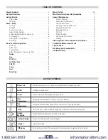
Page 2: ...odic Service 13 Analyzer Re Certification 13 Cleaning 13 Other Important Factors Related To Combustion 14 Combustion Measurement Terms 14 Specifications 15 Electromagnetic Compatibility 15 Limited Warranty 16 DISPLAY SYMBOLS Excess Air Theoretical amount of air in excess of level needed to completely burn fuel Delta T Differential temperature Losses Losses calculated from oxygen and type of fuel I...

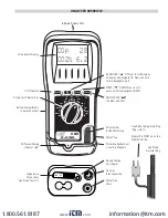
Page 3: ...igate DOWN SEND ENTER to Select and Print Particle Filter Inside Water Trap Water Trap Protective Rubber Boot w built in Magnets Battery Charge AC Adapter Flue Gas Inlet Connection Water Trap Drain 2 Line Backlit Display On Off Button Rotary Test Selector Dial Battery Compartments in back under boot AC Power Charge Indicator Light Temperature Connections Flue Probe Temp T1 Flue Probe Temperature P...

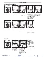
Page 4: ...nce all digits are set Press ENTER to complete setting the date once all digits are set C85 L O N G L I F E E O S A N A L Y Z E R CO2 CO TEMP Menu Status Aux Eff X Air O2 CO Air Free CO2 CO Temp Fuel Date Time MENU SET TIME C85 L O N G L I F E E O S A N A L Y Z E R CO2 CO TEMP Menu Status Aux Eff X Air O2 CO Air Free CO2 CO Temp Fuel Date Time SET TIME 08 30 15 _ C85 L O N G L I F E E O S A N A L ...

Page 5: ...O Temp Fuel Date Time AUXPAGE1 EXIT C85 L O N G L I F E E O S A N A L Y Z E R CO2 CO TEMP Menu Status Aux Eff X Air O2 CO Air Free CO2 CO Temp Fuel Date Time AUX PAGE2 C85 L O N G L I F E E O S A N A L Y Z E R CO2 CO TEMP Menu Status Aux Eff X Air O2 CO Air Free CO2 CO Temp Fuel Date Time AUX EXIT AUXPAGE1 LINE 2 shows press Send to continue to set line 2 Press s UP or t DOWN select between availa...

Page 6: ...CO Temp Fuel Date Time HEADER HEADER2 C85 L O N G L I F E E O S A N A L Y Z E R CO2 CO TEMP Menu Status Aux Eff X Air O2 CO Air Free CO2 CO Temp Fuel Date Time _PHONE NUMBER C85 L O N G L I F E E O S A N A L Y Z E R CO2 CO TEMP Menu Status Aux Eff X Air O2 CO Air Free CO2 CO Temp Fuel Date Time HEADER EXIT The existing HEADER 1 will display with the cursor underneath the first digit Press s UP or ...

Page 7: ...E R CO2 CO TEMP Menu Status Aux Eff X Air O2 CO Air Free CO2 CO Temp Fuel Date Time DEL ALL YES PRINT SETUP Rotate dial to Menu Rotate dial to Menu Press s UP or t DOWN to REPORT Press ENTER Press s UP or t DOWN to PRINTING Press ENTER Press s UP or t DOWN to DEL ALL Press ENTER to proceed Press s UP or t DOWN to select printer Press ENTER to select Analyzer will automatically return to the menu P...

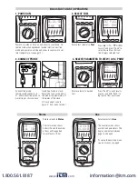
Page 8: ... is approximately at the center of the stack 4 stack adjust cone to aprox 2 from end of probe Rotate selector to desired test Rotate selector to Status The status menu shows battery life and the number of days until suggested re certification CAL Rotate selector to Aux The auxilliary menu shows user defined parameters The display alternates between page 1 and page 2 To set up the auxilliary menu s...

Page 9: ...Free The O2 CO Air free screen shows the calculated amount of O2 from CO2 measured and fuel selected and CO Air Free CO Air free is a calculated value for carbon monoxide as if there were no dilution from air COppm 20 9 20 9 O2 measured Rotate test selector to Fuel The fuel selector position will display the current fuel being used for calculations Press s UP or t DOWN to scroll and press ENTER to...

Page 10: ...tion O2 CO Stack Temp Efficiency Hi Low fire Gas Pressure Send and Return Water temp 80 Furnace Verify proper combustion O2 CO Stack Temp Vent Pressure Efficiency Verify Set Up Gas Pressure Test Limit Switch Pressure Switch Verify proper operation Static Duct Pressure Temperature Rise AC side Static Pressure Drop across coils 90 Furnace Verify proper combustion O2 CO Stack Temp Vent Pressure Effic...

Page 11: ...o 9 O2 Stack Temperature 325 to 500 F Draft Water Column Inches 02 to 04wc Carbon Monoxide parts per million 100ppm Gas Fired Power Burners Oxygen 3 to 6 O2 Stack Temperature 275 to 500 F Stack Draft Water Column Inches 02 to 04wc Overfire Draft Water Column Inches 02wc Carbon Monoxide parts per million 100ppm Oil Fired Burners 2 Oil Fuel Oxygen 4 to 7 O2 Stack Temperature 325 to 600 F Stack Draft...

Page 12: ...ter MUST be changed when it appears discolored on the inner surface Remove water trap assembly from the analyzer as shown above Remove the filter and plastic holder from the housing Discard the filter element but keep the holder to fit to the new filter Clean the inside of the filter housing with a suitable soft cloth Fit the holder onto the new filter element and then insert into the housing Refi...

Page 13: ...stent with local disposal regulations WARNING Repair and service of this instrument is to be performed by qualified personnel only Improper repair or service could result in physical degradation of the instrument This could alter the protection from personal injury this meter provides to the operator Perform only those maintenance tasks that you are qualified to do Remove the probe from the flue a...

Page 14: ... and the stack tempera ture and then reference a slide scale that would give you the relative efficiency number UEi s electronic combustion analyzers perform the measurements on a continuous basis and can calculate the efficiency as adjustments are being made Combine this with a printout and you are able to provide a before and after comparison of the combustion equipment in relatively little time...

Page 15: ...s certified to be compliant The European Council Directive 89 336 EEC requires that electronic equipment does not generate electromagnetic disturbances that exceed defined levels and has an adequate level of immunity to enable it to be operated as intended Since there are many electrical products in use that pre date this Directive and may emit electromagnetic radiation in excess of the standards ...

Page 16: ...Canadian customers we have a recertification service center in Vancouver BC which is ISO IEC 17025 2005 accredited and offers NIST certification services for select products All recertification services are warranted for one year Save time with online recertification check in by visiting www ueitest com and click the SERVICE REQUEST banner and filling out the form Our current recertification price...

Reviews: