background image

20

POWERING OFF

When you power off the C161, there is a 10 second purge.

Make sure you do not exceed the analyzer’s operating specifications. In particular:

 •  Do not exceed the flue probes maximum temperature (1112˚F)

 •  Do not exceed the analyzer’s internal temperature range

 •  Do not put the analyzer on a hot surface

 •  Do not exceed the water trap’s level

 •  Do not let the particle filter become dirty and blocked

View the displayed data to ensure that the stable operating conditions have been achieved and the readings are within the expected 

range.

POST TEST


Remove the probe from the flue and allow analyzer to purge with fresh air 

until readings return to zero. O

2

 to 20.9%, CO to Zero (Be careful the probe 

tip will be HOT).

GENERAL MAINTENANCE

•  Re-certify your instrument annually to ensure it meets original performance specifications.

PERIODIC SERVICE 

WARNING

Repair and service of this instrument is to be performed by qualified personnel only. Improper repair or service could 

result in physical degradation of the instrument. This could alter the protection from personal injury this meter provides 

to the operator. Perform only those maintenance tasks that you are qualified to do. 

•  Keep your instrument dry. If it gets wet, wipe dry immediately. Liquids can degrade electronic circuits.
•  Whenever practical, keep the instrument away from dust and dirt that can cause premature wear.
•  Although your instrument is built to withstand the rigors of daily use, it can be damaged by severe impacts. Use reasonable  


caution when using and storing the meter.

COLD WEATHER PRECAUTIONS

It is important you keep your flue gas analyzer in a warm and dry place overnight

Electronic devices that become really cold, by being left in a vehicle overnight, suffer when taken into a warm room the next    

morning. Condensation may form which can affect the analyzer’s performance & cause permanent damage. See operating and storage  

temperature specifications. 

Electrochemical sensors used in flue gas analyzers can be affected by condensation or water being sucked into the analyzer, as the 

small apertures on top of sensors can become blocked with water, stopping sensors seeing flue gas. When this happens, oxygen or 

carbon dioxide reading will display as “—” & sensors may be permanently damaged

If you think that your analyzer is affected by condensation or water ingress, it may be possible to rectify the problem yourself. Simply 

leave the analyzer running in a warm place, with the pump ‘ON’ sampling fresh air for a few hours (use mains adapter/battery charger if 

needed). If, after doing this, you still experience problems please contact our Service Center.

STATUS

FLUE 1

AUX

FLUE 2

TEMP

Combu

stion Analy

zer

C161

CO

  C

O2

  T

EM

P

Summary of Contents for C161C

Page 1: ...40 Fax 503 643 6322 www ueitest com Email info ueitest com INSTRUCTION MANUAL ENGLISH Residential Combustion Analyzer Combustion Analyzer C161 CO C O 2 T E M P Status v3 Aux O2 Eff CO CO2 Temp Exch Te...

Page 2: ...yout 10 Status Bar Menu Options 10 Status Bar Options Table 10 Menu 11 Using the Menu 11 Stored Logs Memory 12 Menu Options 12 Viewing Stored Logs 13 Log View Menu Options 13 Navigating Stored Logs 13...

Page 3: ...o are familiar with the hazards of their trade Observe all recommended safety procedures that include proper lockout utilization and use of personal protective equipment that includes safety glasses g...

Page 4: ...odule is fitted K Down Button Short press to navigate DOWN L ENTER Button Short press select current option displayed Long press to activate some menu items M Rotary Selector Dial N Particle Filter in...

Page 5: ...3 Aux O2 Eff CO CO2 Temp Exch Test Serial No Sensors Fitted CO CO2 NO O2 T2 T1 B C D E F G H I J K L M W V X P O N S U T R Q Flue Probe Temperature Plug Plugs into T1 Narrow Pin MUST be on the Right h...

Page 6: ...PRE TEST CHECKLIST SETTING INLET TEMPERATURE ANALYZER CONNECTIONS Turn on and zero the analyzer without the flue probe connected to use ambient temperature Connect flue probe thermocouple to T1 during...

Page 7: ...o CO2 Zero On the Purge option short press the Edit Button and a 60 second Purge will begin STATUS F L U E 1 AUX FLUE 2 T E M P P EMPTYING CLEANING THE IN LINE WATER TRAP CHANGING THE PARTICLE FILTER...

Page 8: ...fgc except for Heavy Oil and Pellets O2 Ref Selectable parameter select between 0 0 to 20 0 Logs if logs are saved they will be displayed Code for Authorized Service Personnel only Status Screen Ti Am...

Page 9: ...G Butane Propane Natural Gas Bio Oil Ambient temperature around the analyzer Current atmospheric pressure mBar Shows number of days until next calibration is due Status Bar User Interface The large si...

Page 10: ...Status Bar will offer the user Menu items based on the Selector Dial setting Status Bar Options Table Test Screen Dial Digital Position Test Screen Status Info Available STATUS AUX O2 Eff CO CO2 TEMP...

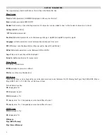
Page 11: ...ess and buttons to change field contents Press to enter content selected Menu Items MENU Sub Menu OPTIONS COMMENTS Time HH MM SS 24 Hour Format e g 7AM 0 00 00 7PM 19 00 00 Date DD MM YY Header LINE 1...

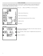
Page 12: ...sage status simply navigate to menu LOGS press the button to select the Log desired Number of stored Combustion Logs Number of stored Auxiliary Logs Number of stored Temperature Logs and Pressure if f...

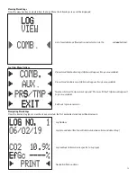
Page 13: ...ll be displayed Log Number Log time and date this line will alternate between time and date of Log Log readings information is specific to Log type Navigation Menu options STATUS F L U E 1 AUX FLUE 2...

Page 14: ...of the selected type Option will only appear if there is more than one Log Navigate to the previously selected Log of the selected type Option will only appear if there is more than one Log Exit back...

Page 15: ...k gas and an increase in the Excess Air In some sealed systems the fresh air drawn in through the breach may reduce the combustion air available leading to an increase in the CO reading If either of t...

Page 16: ...PRINT BUTTON again UEi Infrared Printer Make sure the printer is switched on ready to accept data and its infrared receiver is in line with the analyzer s infrared emitter on top of the analyzer Combu...

Page 17: ...1 3 in accordance to 1st German Feder al Emission Control Ordinance Bim5chV Operating Conditions Temperatures Humidity 32 to 113 F 0 to 45 C 15 to 90 RH non condensing Power Supply Rechargeable batte...

Page 18: ...rs Draft Verify proper combustion O2 CO2 CO Stack Temp Efficiency Hi Low fire Gas Pressure Supply and Return Water temp 80 Furnace Verify proper combustion O2 CO2 CO Stack Temp Vent Pressure Efficienc...

Page 19: ...atic Duct Pressure Temperature Rise AC side Static Pressure Drop across coils WHAT RESULTS ARE GENERALLY ACCEPTABLE What Results Are Generally Acceptable Atmospheric Gas Fixed Burners Gas Fired Burner...

Page 20: ...s can degrade electronic circuits Whenever practical keep the instrument away from dust and dirt that can cause premature wear Although your instrument is built to withstand the rigors of daily use it...

Page 21: ...the protective rubber boot and fit 3 AA NiMH rechargeable batteries in the battery compartment Take great care to ensure they are fitted with the correct battery polarity Replace the battery cover an...

Page 22: ...ombustion analyzers have a standard 1 year warranty Each recertification extends the warranty for 1 more year for up to 10 years from the date of purchase Contractors who book recertification of a C16...

Page 23: ...measure the CO2 level and the stack temperature and then reference a slide scale that would give you the relative efficiency number UEi s electronic combustion analyzers perform the measurements on a...

Page 24: ...red or replaced at UEi s option This warranty covers normal use and does not cover damage which occurs in shipment or failure which results from alteration tampering accident misuse abuse neglect or i...

Reviews: