background image


36

21

610.592A

Rev.

1

UDEVAC-500


Equipment configuration:

System Requirements:
AMD / Inter CPU 2.0G, Windows XP SP3 / Window 7/8 / 8.1 / 10.

Installation.

Double click on “SF-500.exe” The installation will be done in a transparent way for the user, and will finish with 
the creation of a shortcut to the SF-500 application on the desktop of the computer.

Nota: 

Right click on the "SF-500" shortcut and select properties to run the application as administrator.

Description

Configuration and use of the software

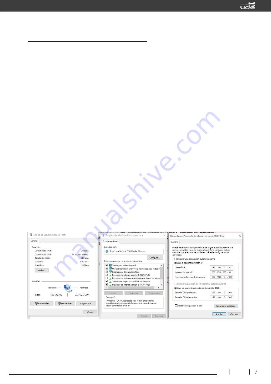
Put the PC and the SLA-500M equipment in the same IP number range

Device's default IP address:  192.168.1.168
 Sub Mask: 255.255.0.0, 
Gateway: 192.168.1.1. 

Put down the 5th switch of the configuration DIP switch on the rear panel of the main unit to have the static IP 
address assignment.

Go to control panel select 

Network and Internet

, select 

Network and Sharing Center

, select 

Local Area 

Connection

 when the window appears as below, select 

Properties

, in connection properties select "Internet 

Protocol version 4 "and press properties and then the 

Internet Protocol Properties

 window opens where we 

can change the IP of the computer

SF-500 Configuration software

Summary of Contents for UDEVAC-500

Page 1: ...Installation and configuration manual UDEVAC 500 36 1 rev 0 EQUIPOS Y SISTEMAS MEGAFONÍA INTERCOM PUBLIC ADDRESS SYSTEMS ude udeaudio com BARCELONA SPAIN Tel 34 934 772 854 34 609 914 787 EN 54 ...

Page 2: ...al characteristics Operation guide Background music broadcast Automatic emergency broadcast Manual emergency emission Warning with the emergency microphone General announcement or by zones through the microphone desk SLA 500SF Software Description Configuration and usage Introduction to icons Configuration software operation Menu bar and tools System Control Config Window Control Window State Wind...

Page 3: ...s D integrated amplifier Automatic issuance of evacuation and alert messages and up to 255 voice messages to pre established zones Customizable alert and evacuation messages stored on a SD card Supervision of loudspeaker linesA B spare amplifier and backup power supply Expandable capacity up to 120 zones using SLA 500S expansion modules Connection of up to 32 PZ 500 or PZ 500F remote microphones T...

Page 4: ...ailure 255 evacuation messages available 6 speaker zones with a maximum power of 500W either in a single zone or distributed among all 6 signal inputs for connecting analog microphones or external music sources Maximum recording capacity of up to 1000 events in the system log Connection of up to 32 PZ 500 or PZ 500F remote microphones The system supports redundant cabling ring connection between t...

Page 5: ...fails or is not connected or configured Off No logical or physical connection between the control equipment and the expansions 4 Fault indicator Yellow System failure press FAULT ACK to silence the alarm tone although the LED will continue to flash Verify source of failure to restore system to normal mode Off System is working properly unless the monitoring function is disabled 5 Emergency microph...

Page 6: ...ress the FAULT ACK button to stop the indicator flashing and the buzzer until the equipment works normally the FAULT will stay on solid 9 9 EVAC evacuation message button and indicator Green Evacuation message is playing Yellow Evacuation voice message or SD card has been lost Off Everything is working in normal mode Note 1 If any user wants to manually play the evacuation voice message they must ...

Page 7: ...message is being broadcast in a zone When an evacuation or alert message is playing the indicator will light 15 Indicator that the zone is playing background music In general it is recommended to first select the zone or zones where you want to hear an audio signal and then select the audio input to be played in these zones This selection and redirection of audio input signals to zone groups can a...

Page 8: ...tion must be done using the SF 500 software 3 DC24V outputs for 4 wire attenuators For installations with a four wire attenuators system Limited output current for each output 0 2A Note the output cannot exceed a total power of 28W 4 Programmable control outputs These outputs will usually remain open these outputs can be programmed with the SF 500 software to activate or deactivate with automatic ...

Page 9: ...SD memory card SD memory card supports a maximum of 255 messages Never handle this card with the equipment turned on Do not delete or manipulate the files if you are not sure make a backup copy of the original files before making any changes otherwise the equipment may stop working and will not come under warranty VERY IMPORTANT THE AUDIO FILES MUST BE IN WAV FORMAT In the root directory of the SD...

Page 10: ...on equipment functions DIP DIP switches for configuration of functions of the control or expansion equipment Up means enable and down means disable SLA 500M main equipment Switch 1 above activates the general supervision of the system amplifier speaker lines etc Down disables supervision Switch 2 above activates emergency power supervision Down disables emergency power supervision Switch 3 above e...

Page 11: ...70dB Control input departure Fault output Closed circuit no voltage EVAC Output status Closed circuit no voltage EVAC input Reset Closed circuit no voltage T 0 5s 8 control outputs Closed circuit no voltage 8 control inputs Way 1 closed circuit no voltage Emergency message Format WAV Memory card SDmemorycard Capacity 32G No of messages 255 Max Period 10 years SD Card Format FAT FAT32 Log events Fo...

Page 12: ...recorded messages in case of emergency Top priority supervised PTTmicrophone Microphone signal monitored in real time Configurable as PTTor normal 24V DC phantom power from SLA 500M or SLA 500S Status LEDs forAC DC Fault Mic andTest Communication distance up to 600 meters Up to 32 fireman microphones supported in the system Redundant connection in loop mode with the rest of the system s devices us...

Page 13: ...cy mode Off equipment is normal mode To make an emergency warning broadcast A Activate emergency mode by pressing the red button with cover and immediately the red light will start flashing and then press the EVAC MSG or ALERT MSG buttons which will activate the warning in all zones of the system B The automatic transmission of an emergency will be activated by closing any of the rear inputs remot...

Page 14: ... 9 Lock 10 Hand microphone It is mainly used to guide people in an emergency situation 11 Wiring entry 12 DIP switch for setting the device ID addressing Configuration of the ID of the equipment by means of the DIPs Raised in position ON means that it is activated and lowered means disabled From the 1st to the 5th switch are to configure the address identification of the microphone through a binar...

Page 15: ...than 3W MIC Performance SPL 30mV Mechanical specifications 298 x 298 x 89 mm Net weight 3 8KGS Installation Desktop Colour Black Environmental requirements Operating temperature 5ºC 40ºC Storage temperature 20ºC 70ºC Relative humidity 95 without condensation Less than 0 2A with 24V power all LEDs on and in voice prompt mode ...

Page 16: ...32 looping microphones Remote microphone of the Digital Voice Evacuation System Microphone with 12 zone capacity It can be expanded to 12 more zones through PZ 500E The system supports 32 remote looping microphones 12 zone selection buttons with three color indicators Two RJ45 ports for link input and output Communication cable or CAT6 up to 600 meters Description Main characteristics Microphone d...

Page 17: ...lection buttons 5 All zones selection button ALL Used to select all zone groups 6 Voice announcement Start Button To start voice prompts with the microphone Description of operation 1 When a voice announcement is being made if we press this button the voice announcement will end 2 When there is no voice prompt and a zone is selected press this button to start the voice prompt you need to wait for ...

Page 18: ...hone indicator LEDs normally up lower and raise it immediately to perform the test 8 End of line resistor Above indicates disabled below indicates enabled 1 000000 2 100000 3 010000 4 110000 32 111110 Nota 1 If the PZ 500F PZ 500 PZ 500P or SLA 500S cannot communicate normally with the main equipment SLA 500M activate the end of line resistor of the last connected equipment at the end of the line ...

Page 19: ...zones 12 zones o 12 groups Announcements mode PTT or normal mode Electrical parts Supply Voltage 20V 27 5V Maximum Current 0 1A Consumption 2 4W Line input Sensitiviy 775mV Impedance 10k Ω S N Ratio 70dB Microphone input Sensitiviy 5mV Impedance 600Ω Working environment Working temperature 5 40 Storage temperature 20 70 Relative humidity 95 Mechanical part Dimensions 240 W x 140 D x 55 H mm Weight...

Page 20: ...n or remote reset input again to end the emergency broadcast Manual activation of the emergency message Press the emergency button it will light up red then select the zone and press the EVAC MSG or Alert MSG button For the manual emergency broadcast to work the message indicator light and the zone evacuation light must be on Press the emergency button or remote reset input again to end the emerge...

Page 21: ... use of the software Put the PC and the SLA 500M equipment in the same IPnumber range Device s default IPaddress 192 168 1 168 Sub Mask 255 255 0 0 Gateway 192 168 1 1 Put down the 5th switch of the configuration DIP switch on the rear panel of the main unit to have the static IP address assignment Go to control panel select Network and Internet select Network and Sharing Center select Local Area ...

Page 22: ...ur DHCP server Introduction to icons Save and synchronize with the SLA 500M equipment each revision must click this OK button Save but do not synchronize with the SLA 500M Zone impedance variation open circuit or short circuit Cancel the action The current zone is normal no audio is playing The current zone is disabled for operation The current zone is on emergency broadcast The current zone is op...

Page 23: ...he current equipment is working with an error or is faulty Some module of the system is defective or faulty Update The current equipment is operating normally Upload Save Host 01 SLA 500M Host 02 SLA 500S Host 36 23 610 592A Rev 1 UDEVAC 500 ...

Page 24: ...e software closes after entering the wrong password 3 times Synchronize Once we give OK in the LOGIN window the connection of the SF 500 with the SLA 500M will start a synchronization bar will appear like the image below and then the Main Page will be displayed Software main page At the top is the toolbar In the left window is the configuration options tree in the center is the system status windo...

Page 25: ...menu bar and tools Enter with password and username the default username is admin and the password is empty Save a schedule Delete log Exit the program Download firmware Exit the program Import a schedule Configuration of network parameters Software version information ...

Page 26: ...an evacuation or alert message being activated Group to configure the parameters of the groups of zones allows us to create groups of speaker zones according to the number of expansion units that we have configured LOG to check the events that have occurred in the equipment such as alarms module failures impedance changes etc Audio priority Line audio mode to configure the parameters of the priori...

Page 27: ...s that there is a fault or breakdown If the user changes the SD card please use a card in FAT32 file format to prevent malfunctions do not put other files in evacuation or alert folders and evacuation or alert messages must be in WAV In this window we can see the status of the audio inputs When any group is selected including ALL ZONES in 5 click on any of the line audio inputs to output the audio...

Page 28: ...he SLA 500M control equipment including the equipment itself STATE EQUIPMENT ID In this window the State will indicate the status of the equipment A green tick means that it is connected and working correctly if there is a red X it indicates a failure in the connection or in the equipment itself Equipment ID informs us of the type of equipment amplifiers microphones etc Host 01 Paging 01 etc ...

Page 29: ... the speaker zones enabled so that they work In this window we can select the speaker zones that have impedance supervision enabled The minimum power required in each line for correct impedance supervision is 20W In this window we can select each of the computers Host01 02 03 etc previously configured in window 1 PAGING In this window we can select the number of microphone desks that the system wi...

Page 30: ...ntrol the music and speaker lines of the specified main equipment Selecting this button will open the window where we can configure which zone or zones this button is activated by selecting in window 12 You can select a single zone several zones or all zones including expansion equipment zones We can see the expansion equipment zones if we select the expansion equipment with the arrow buttons Host...

Page 31: ...e message is played only once Host contact config In this window we can select the device Host 01 Main device Host 02 Expansion device Host 03 Expansion unit etc in order to configure the alarm activation inputs of each of the units In this window we can select the evacuation message or the alert message to be used as an emergency message in case of fire In this window we can select the input cont...

Page 32: ...e all the hit zones by means of the arrows and Nota Please click OK after modifying the settings to save those settings We can select one or more of the output relays that will be activated with the input contact that we are programming at this moment We can see the information of the equipment and the contact entries in addition if specific zones have been selected it will also appear which zones...

Page 33: ...ipment Host 02 Host 03 etc ID is a number that is added automatically by the system and cannot be modified AUDIO NAME is the name of the audio input microphones evacuation audio messages etc it is added automatically by the system and cannot be modified PRIORITY means the priority of the audio of each of the inputs but also note that if an input of higher priority than the current audio output is ...

Page 34: ... card SD They are activated when any of these emergency messages are launched Description On the left side of the panel SLA 500M or the SLA 500S panel line output control knob SF 500 just shows current effective line output SF 500 system group can be set from 0 120 by system configuration Equipment parameter to confirm the group number the default is six each zone in the group can be set by Group ...

Page 35: ...rning impedance change in a speaker zone etc it can be used for searching when there are many records DETAILED will inform us of the details of the type of event that has occurred Description The user can filter certain events in the log choosing the start and end date and time or type of record log type and also save it on the computer as an Excel sheet by pressing the Window Log ...

Page 36: ...plication otherwise your settings your settings will not be saved Update System Time Data and Time means date and time this is the current time and date of the equipment Auto In auto mode the date and time are automatically synchronized by software After editing please click Application otherwise your settings will not be saved Set the maximum tolerance for the impedance variation of speaker lines...

Reviews: