SARA-R42 - Application note
UBX-20050829 - R02
Testing
Page 44 of 58
C1-Public
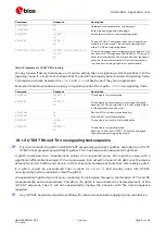
Command
Response
Description
AT+UTEST=10,1
(pin description returned)
OK
Gets the pin information.
AT+UTEST=10,2,"000000000000
000000000600"
OK
The command puts the module in Interface initialized
state; the command saves the pins status to restore it
at the end of the test. Pins enabled for testing: RTS pin
10, CTS pin 11
Where hex: 0000 0000 0000 0000 0000 0600
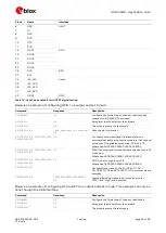
AT+UTEST=10,3,"000000000000
000000000000"
OK
RTS and CTS are configured for output where the bits
for the pins 10,11 are set low
Where hex: 0000 0000 0000 0000 0000 0000
AT+UTEST=10,4,"000000000000
000000000600"
OK
RTS and CTS is set to high for pin 10, 11
Where hex: 0000 0000 0000 0000 0000 8000
AT+UTEST=10,5
Configurations made by the AT+UTEST=10,2;
AT+UTEST=10,3 and AT+UTEST=10,4 commands are
executed.
AT+UTEST=10,6
000000000000000000000600
OK
Logic digital value measured at modules pins for
GPIO1, and "high" level detected.
•
When a module is programmed to enter the end user test mode, the
+CFUN: 5
URC will be reported
if the module is in non-signaling mode, and it can be used as an indication the module does not exit
properly the non-signaling mode.
☞
If the +UGPIOC, +UGPIOR, and +UGPIOW AT commands are used in the same power-up session,
then apply these commands before applying the AT+UTEST=10 command. This will allow the
AT+UTEST=10 command to interact with the pins effectively, and not have conflicting control
with the other commands.
10.2
Network simulators testing
When testing with network simulators, such as a CMW500 from Rohde & Schwarz as one example
among many, the simulator may not be configured to release the RRC connection when there is an
idle period.
By means of the +UMACQOSTMR AT command, this timer may need to be disabled to allow certain
measurements. RF sensitivity measurements, for example, expect the RRC connection to remain in
the connected state. If this MAC QoS timer is not disabled, then after the timer expires, it will release
the RRC connection with the simulator and may interrupt the measurement.
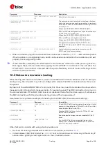
Here below it is reported an example of checking for the MAC QoS timer value and setting it.
Command
Response
Description
AT+UMACQOSTMR?
+UMACQOSTMR: 90,120
OK
Check if MAC QoS timer is enabled by reading it. In this
example, it is enabled for LTE Cat M1 with 35 s, while it
is enabled for NB-IoT with 120 s.
AT+UMACQOSTMR=0,0
OK
Disabled MAC QoS timer for both LTE Cat M1 and
NB-IoT with 0 value set.
AT+CFUN=15
OK
Reset the device for new value to disable MAC QoS
timer.
AT+UMACQOSTMR?
+UMACQOSTMR: 0,0
OK
Confirm MAC QoS timer is disabled, which in this
example it is
reflected as disabled with “
0
” value for
both LTE Cat M1 and NB-IoT.
Other factors to consider with using a test simulator are:
•
the need for utilizing a dedicated test SIM: for more details, see section
•
in Radio Bearer (RB) Test Mode, the
+CGDCONT
test command does not show any APN and any IP
address after getting a valid registration on the simulated network.


