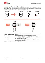
EVK-NINA-B4 - User guide
UBX-19054587 - R04
Board configuration
Page 18 of 40
C1 - Public
Battery powered, 3
–
1.7 V
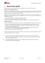
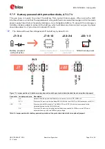
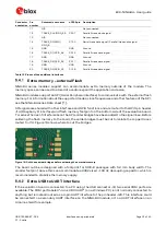
When using a battery, Figure 10 shows the default configuration. The battery voltage is connected to
VDD_NINA, which in turn, is connected to the NINA-B4 VCC supply. If needed, a jumper can be added
to J22 pins - 2 and 4 to supply LEDs and other peripherals with power, as long as this does not exceed
the maximum current rating of the battery. If the NINA module has to be configured, the VDD_MCU
net can be connected to enable PC communications by adding a jumper to J7 pins 9 and 10.
☞
Jumpers must be connected to both J7: 9
–
10 and J22: 2
–
4 to be able to communicate with the
NINA module from a PC. If possible, the EVB power configuration should be switched to the
default 3.3 V configuration, as connecting an extra board peripheral might deplete the battery.
⚠
Do not connect jumpers J7: 5
–
6 and J7: 7
–
8 at the same time while a battery is connected. This
might cause damage to the battery.
Figure 10: Jumper positions for battery powered operation, the jumpers shown in dashed lines are optional
Connector
Add jumper to pins
Description
J7
5, 6
Selects the battery connected to the battery holder as source for the VDD_NINA net.
9, 10
(Optional) Powers up the Interface MCU, USB hub, and UART to USB converter with 3.3 V.
J22
1, 3
Powers up the NINA module. The NINA VCC and VCC_IO pins are connected to the
selected source for the VDD_NINA net.
2, 4
(Optional) Powers up the peripherals directly connected to NINA such as LEDs and
external memory with the NINA supply voltage.
Table 4: Jumper positions for battery powered operation, two jumpers are optional
J7
B
O
ARD
BA
TT
3V3
3
4
2
1
J22
V
C
C
_IO
V
C
C
5
6
9
10
NINA module power
board I/O power
(optional)
J22: 2-4
J22: 1-3
PC communication
(optional)
MCU
J7: 9-10
Battery powered
J7: 5-6


