background image

23

Accessing the Configuration Portal

Wireless Settings 

To use the mPort Serial on a Wi-Fi 

network, configure the Wireless Settings:

a.  Click Scan for a list of available SSIDs. Select the 

appropriate SSID or type in the name manually in 
the SSID field.

b.  Select the appropriate Security and Authentication 

settings for your network.

c.  Enter your network key.

After you’ve entered the necessary settings, click Change
You will be asked to apply the changes; click Apply.
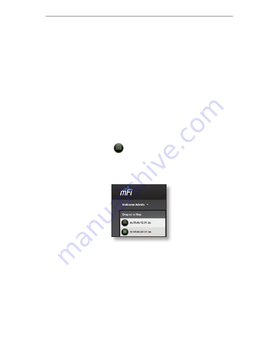
4.  Log in to the mFi Controller. 
5.  The mPort Serial 

 icon appears in the left panel 

under the Drag on to Map heading. Once you’ve 
customized your map, you can position the mPort 
Serial in the appropriate location.


For additional details on the mFi Controller software, refer 
to the User Guide on our website at www.ubnt.com/mfi

Summary of Contents for mPort-S mPort Serial

Page 1: ...mFi Networked Serial Interface Model mPort S...

Page 2: ......

Page 3: ...and define automation rules using your web browser Package Contents mPort Serial Wall Mount Bracket PoE Adapter and Power Cord Antenna mPort Serial Model mPort S Terminal Block Screws Qty 4 Anchors Qt...

Page 4: ...n active Ethernet connection is made and flash when there is activity Status The Status LED will light yellow when the mPort Serial is first powered on in factory default mode out of the box The Statu...

Page 5: ...switch router or other device for remote access Serial TB Terminal Block Port Connects to an industrial networking device for automation such as script execution from the mFi Controller software USB...

Page 6: ...rdware Installation Remove the Wall Mount Bracket from the mPort Serial by pressing the Release Tabs Release Tabs Wall Mount Optional 1 Position the Wall Mount Bracket with the Release Tabs on top Rel...

Page 7: ...e a 6 mm drill bit to drill the holes in the wall c Insert the four Anchors into the wall d Insert the Screws into the anchors 3 Angle the mPort Serial so that the notches on the bottom of the Wall Mo...

Page 8: ...rial Antenna Installation Optional The mPort Serial uses the internal antenna by default If you want to use an external antenna then attach the included Antenna and configure its use in the mFi Contro...

Page 9: ...cable not included Note Only one serial port can be used at a time Serial DB9 1 Connect one end of the serial cable to the console port of the switch router or other device Note A null modem may be n...

Page 10: ...for RS232 RS422 and RS485 For more information refer to the mFi User Guide available at www ubnt com mfi Function RX TX Ground Pinout R R T T G RS232 RS422 RS485 Technically not needed 1 Wire one end...

Page 11: ...9 Connecting a Serial Device 2 Wire the other end of the serial cable to the Terminal Block included with the mPort Serial 3 Insert the Terminal Block into the Serial TB port of the mPort Serial...

Page 12: ...Port Serial Connecting Ethernet and Power 1 Connect an Ethernet cable to the Ethernet port on the mPort Serial 2 Connect the other end of the Ethernet cable to the Ethernet port labeled POE on the PoE...

Page 13: ...ial can be configured via LAN or by connecting an Ethernet cable directly from your computer to the LAN port on the PoE Adapter For details refer to Accessing the Configuration Portal on page 19 4 Con...

Page 14: ...e you add another mFi device Note If you are using the cloud there is no need to install the mFi Controller software locally Skip to Accessing the Configuration Portal on page 19 The mFi Controller so...

Page 15: ...load and Installation 2 Click Continue and follow the on screen instructions to install the software 3 Go to Go Applications and double click the mFi icon Proceed to Configuring the mFi Controller Sof...

Page 16: ...14 mFi mPort Serial PC Users 1 Launch mFi installer exe 2 Click Install 3 If your computer doesn t have Java 1 6 or above installed you will be prompted to install it Click Install to continue...

Page 17: ...oftware Download and Installation 4 Ensure that the Start mFi Controller after installation option is checked and click Finish Note The mFi Controller software can also be launched from Start All Prog...

Page 18: ...e 1 The mFi Controller software startup will begin Click Launch a Browser to Manage the Network 2 The mFi Configuration Wizard will appear the first time you launch the mFi Controller software On the...

Page 19: ...ct the device s that you want to configure The Refresh button can be used to refresh the list of devices Click Next to continue 4 Enter an administrator name in the Admin Name field Enter a password i...

Page 20: ...18 mFi mPort Serial 5 Click Finish to confirm your settings 6 A login screen will appear for the mFi Controller management interface Enter the Admin Name and Password that you created and click Login...

Page 21: ...r to the LAN port on the PoE Adapter and configure your computer with a static IP address Connect an Ethernet cable from your DHCP enabled LAN to the LAN port on the PoE Adapter Configuration Portal v...

Page 22: ...1 Launch the Ubiquiti Device Discovery Tool 2 A list of Ubiquiti devices on the network will appear Locate the appropriate device named M2S under Product Name and double click it Note If you have mor...

Page 23: ...er ubnt in the Username and Password fields Note Once a device has been connected to the cloud the Configuration Portal login information changes The new username password combination can be found on...

Page 24: ...is the IP address and http port used by the Controller The port is usually 6080 for example 192 168 25 161 6080 or mfi acme com 6080 For cloud users this is mfi ubnt com b Enter the User Name and Pas...

Page 25: ...entication settings for your network c Enter your network key After you ve entered the necessary settings click Change You will be asked to apply the changes click Apply 4 Log in to the mFi Controller...

Page 26: ...ntegrated PoE Adapter Included Max Power Consumption 3 W Networking Interface 1 10 100 Ethernet Port Ports 1 DB9 Serial Port 1 Terminal Block Serial Port WiFi Standards 802 11b g n Serial Protocols RS...

Page 27: ...oducts which must be returned by Buyer to UBIQUITI NETWORKS factory freight prepaid No Products will be accepted for replacement or repair without obtaining a Return Materials Authorization RMA number...

Page 28: ...ation or addition has been made to the Product by persons other than UBIQUITI NETWORKS or UBIQUITI NETWORK S authorized representatives or otherwise approved by UBIQUITI NETWORKS III The Product has b...

Page 29: ...ould be provided only by a qualified service technician 3 This equipment is provided with a detachable power cord which has an integral safety ground wire intended for connection to a grounded safety...

Page 30: ...l may cause harmful interference to radio communications Operations of this equipment in a residential area is likely to cause harmful interference in which case the user will be required to correct t...

Page 31: ...cessaire l tablissement d une communication satisfaisante This radio transmitter FCC ID SWX VPS IC 6545A VPS has been approved by Industry Canada to operate with the antenna types listed below with th...

Page 32: ...uetele ja nimetatud direktiivist tulenevatele teistele asjakohastele s tetele Suomi Finnish UBIQUITI NETWORKS vakuuttaa t ten ett UBIQUITI NETWORKS device tyyppinen laite on direktiivin 1999 5 EY olee...

Page 33: ...EF Slovensky Slovak UBIQUITI NETWORKS t mto vyhlasuje e UBIQUITI NETWORKS device sp a z kladn po iadavky a v etky pr slu n ustanovenia Smernice 1999 5 ES Svenska Swedish H rmed intygar UBIQUITI NETWO...

Page 34: ...ional details visit www ubnt com mfi Ceiling Mount Motion Sensor mFI MSC Wall Mount Motion Sensor mFi MSW Temperature Sensor mFi THS Current Sensor mFi CS Door Sensor mFi DS Thermostat Coming Soon 1 2...

Page 35: ......

Page 36: ...w w w u b n t c o m 2012 2013 Ubiquiti Networks Inc All rights reserved Support support ubnt com Wiki Page wiki ubnt com Support Forum forum ubnt com Downloads downloads ubnt com...

Reviews: