Ubiquiti EdgePoint R8 Quick Start Quide Download Page 22

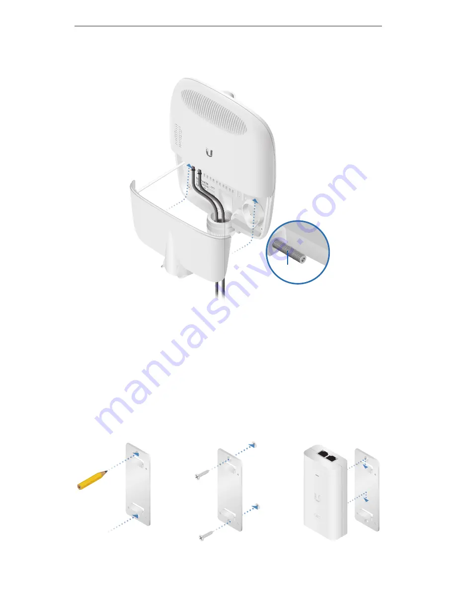
5.  When you are finished, replace the port cover and use an 

S2 hex wrench to tighten the Screw and secure the port cover.

Screw

Mounting the Gigabit PoE Adapter (Optional)

1.  Remove the PoE Mounting Bracket from the adapter, place the 

bracket at the desired location, and mark the two holes. 

2.  Pre-drill the holes if necessary, and secure the bracket using 

two fasteners (not included).

3.  Align the slots on the adapter with the tabs on the PoE 

Mounting Bracket, and then slide the adapter down.

20

EdgePoint EP-R8 Quick Start Guide

Summary of Contents for EdgePoint R8

Page 1: ...Intelligent WISP Control with FiberProtect Model EP R8...

Page 2: ......

Page 3: ...d mast pole tower or grounding bar Shielded Category 5 or above cabling should be used for all wired Ethernet connections and should be grounded through the AC ground of the PoE We recommend that you...

Page 4: ...omes solidly lit the SFP 2 LED is used if there is an SFP module connected to the SFP 2 port After a few seconds the LED will turn off and the EP R8 will automatically reboot Power on Reset 1 Disconne...

Page 5: ...cable also known as a rollover cable to connect the Console port to your computer If your computer does not have a DB9 port then you will also need a DB9 adapter Then configure the following settings...

Page 6: ...A on eth0 PoE In 54V 1 5A on PoE In Power Output Options EdgePoint required Passive 54 24V 4 Pair PoE on eth1 eth2 Passive 24V 2 Pair PoE on eth3 eth7 The number of devices that can be powered depends...

Page 7: ...gabit PoE Adapter to power the EdgePoint and passive PoE output eth1 2 54 24V PoE Out RJ45 ports support 10 100 1000 Ethernet connections and passive 54 24V 4 pair PoE output for airFiber devices eth3...

Page 8: ...d in then the SFP port is active and the corresponding RJ45 port is deactivated Note For extreme temperatures please use industrial grade fiber SFP modules Front Panel LEDs LED State Status eth0 Speed...

Page 9: ...No PoE Amber 54V 4 Pair Passive Green 24V 4 Pair Passive eth3 7 Speed Link Act Off No Link Amber 10 100 Mbps Link Flashing Indicates Activity Green 1000 Mbps 1 Gbps Link Flashing Indicates Activity P...

Page 10: ...or mounting an optional PicoStationM2HP not included to the back of the EdgePoint You can use the PicoStationM2HP for wireless management of the EdgePoint Pole Mount Bracket Used for pole mounting or...

Page 11: ...to attach the Cable Sleeve to the EdgePoint Note You have two options for using a 2 0 inch NPT National Pipe Thread male conduit not included Use the conduit instead of the Cable Sleeve Use the condu...

Page 12: ...d Pole Mounting 1 Open the two Metal Straps and feed them through the mounting slots on the back of the EdgePoint 2 Wrap the Metal Straps around the pole Use a 7 mm socket wrench to turn the screws cl...

Page 13: ...Wall Mount Bracket to the wall Note The Wall Mount Bracket must attach directly to a stud or other structurally stable surface Tab Pointing Up 2 Insert the tabs of the Wall Mount Bracket into the slot...

Page 14: ...3 Use two M8x10 screws not included to attach the EdgePoint to the Wall Mount Bracket 12 EdgePoint EP R8 Quick Start Guide...

Page 15: ...in length 1 Remove the nut from the Ground Bonding Point located on the back of the EdgePoint 2 Attach a ground wire min 10 AWG or 5 mm2 to the lug and replace the nut to secure the wire 3 Secure the...

Page 16: ...to loosen the Screw and remove the port cover from the EdgePoint Screw 2 Feed the Ethernet cables through the Cable Sleeve and connect them to ports in this range eth0 eth7 Note PoE is disabled by de...

Page 17: ...ny Ethernet cable by feeding a cable tie not included through the tie slot under the cable Then wrap the cable tie around the cable and tighten 4 Connect the other ends of the Ethernet cables to your...

Page 18: ...compatible fiber module into the SFP port Note The corresponding RJ45 port will be deactivated 2 Feed the fiber optic cable through the Cable Sleeve and remove the cable jacket from the fiber optic ca...

Page 19: ...D M Tx1 550 nm Rx 131 0nm SN 130 826 179 EF 100 0M 2 0KM 15 50 4 To finish the strain relief a Feed a cable tie not included through the tie slot near the cable opening b Feed an additional cable tie...

Page 20: ...instructions for your installation WARNING 48V is NOT supported Connecting to the VDC Input 1 Wire one end of the DC power cable to the VDC terminal block which uses auto polarity detection 2 Replace...

Page 21: ...e load increases When the voltage drops to the same level as the lower voltage source then the lower voltage source will also start providing power 1 Connect an Ethernet cable to the PoE In eth0 port...

Page 22: ...ptional 1 Remove the PoE Mounting Bracket from the adapter place the bracket at the desired location and mark the two holes 2 Pre drill the holes if necessary and secure the bracket using two fastener...

Page 23: ...Press enter PC or return Mac 3 The login screen will appear Enter ubnt in the Username and Password fields Read the Ubiquiti License Agreement and check the box next to I agree to the terms of this L...

Page 24: ...nfigure the PoE setting For eth1 eth2 select Off 24V 4pair or 54V 4pair For eth3 eth7 select Off or 24V Then click Save Note If the PoE screen states that PoE is not supported then there is insufficie...

Page 25: ...4V 1 4A 4 Pair 1 2 4 5 3 6 7 8 Passive PoE eth1 to eth2 5 24V 0 7A 2 Pair 4 5 7 8 Passive PoE eth3 to eth7 Power Monitoring 1 DC Terminal Block Input Power 2 RJ45 PoE In and eth0 Input Power Supported...

Page 26: ...ualified service technician 3 This equipment is provided with a detachable power cord which has an integral safety ground wire intended for connection to a grounded safety outlet a Do not substitute t...

Page 27: ...made thereto except by Ubiquiti Networks or Ubiquiti Networks authorized representatives or as approved by Ubiquiti Networks in writing II has been painted rebranded or physically modified in any way...

Page 28: ...N INFRINGEMENT AND ANY WARRANTIES ARISING FROM ANY COURSE OF DEALING USAGE OR TRADE PRACTICE IN CONNECTION WITH SUCH PRODUCTS AND SERVICES BUYER ACKNOWLEDGES THAT NEITHER UBIQUITI NETWORKS NOR ITS THI...

Page 29: ...warranties or conditions so the above exclusion may not apply to you You may have other rights that vary from country to country state to state or province to province Some countries states and provin...

Page 30: ...pment generates uses and can radiate radio frequency energy and if not installed and used in accordance with the instruction manual may cause harmful interference to radio communications Operations of...

Page 31: ...the shop where you purchased the product Deutsch Die Europ ische Richtlinie 2012 19 EU verlangt dass technische Ausr stung die direkt am Ger t und oder an der Verpackung mit diesem Symbol versehen ist...

Page 32: ...riel lectrique ou lectronique par les moyens de collecte indiqu s par le gouvernement et les pouvoirs publics des collectivit s territoriales L limination et le recyclage en bonne et due forme ont po...

Page 33: ...I NETWORKS d clare que l appareil UBIQUITI NETWORKS est conforme aux exigences essentielles et aux autres dispositions pertinentes des directives 2014 30 UE 2014 35 UE Deutsch German Hiermit erkl rt U...

Page 34: ...nian Prin prezenta UBIQUITI NETWORKS declar c acest dispozitiv UBIQUITI NETWORKS este n conformitate cu cerin ele esen iale i alte prevederi relevante ale Directivelor 2014 30 UE 2014 35 UE Slovensky...

Page 35: ......

Page 36: ...go the Ubiquiti beam logo airFiber airMAX EdgeMAX EdgeOS EdgePoint EdgePower FiberProtect PicoStation and TOUGHCable are trademarks or registered trademarks of Ubiquiti Networks Inc in the United Stat...

Reviews: