background image

© 2022 Ubicquia, Inc.


31

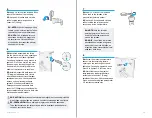
Mount the Rogowski Coils

Instalar las bobinas Rogowski 

secundarias

EN:

 The black (line 1) and red (line 

2) secondary potential wires have 

matching Rogowski coils mounted 

around the bushings. 

ES: Los cables, negro (línea 1) y 

rojo (línea 2) del arnés de potencial 

secundario corresponden a las bobinas 

Rogowski colocadas alrededor de las 

boquillas, por medio de un señalamiento.

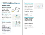
EN:


NOTE:

 The secondary 

Rogowski coils are marked with 

a colored heat shrink. When 

attaching the secondary potential 

cable wires, be sure to match the 

wire color with the corresponding 

Rogowski color marking. (see


Section F. Attach the Secondary 

Potential Cable - Attach the 

Secondary Potentials

).

ES: NOTA: Las bobinas Rogowski 

secundarias están marcadas con 

un plástico termo-contráctil de 

color. Al conectar los cables de 

potencial secundario, asegúrese de 

hacer coincidir el color del cable 

con el color correspondiente de 

la marca de la bobina Rogowski. 

(consulte la sección F. Conectar el 

arnés de potencial secundario - 

Conectar los cables de potencial 

secundarios).

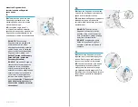
EN:


NOTE: 

The arrow on the 

Rogowski coil must point in the 

direction of the current flow at the 

time of installation, usually pointing 

away from the transformer.

ES: NOTA: Asegúrese de que la 

flecha de las bobinas Rogowski 

apunte en el sentido del flujo de la 

corriente.

11

EN:

 Connect the Rogowski coil ends 

together: insert, then twist slightly until 

locked. Gently tug on the Rogowski 

connector to ensure it is fully seated.

ES: Conecte los extremos de la bobina 

Rogowski acoplando los elementos 

macho y hembra del conector, luego 

gire ligeramente hasta asegurarlos. Tire 

suavemente del conector Rogowski para 

asegurarse de que esté correctamente 

conectado.

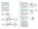
10

EN:

 Open the Rogowski coil and place 

it around the bushing bolt, between the 

spade and the transformer face.

ES: Abra la bobina Rogowski y colóquela 

alrededor del perno de la boquilla, 

entre la terminal tipo paleta y la cara del 

transformador.

Summary of Contents for ubigrid DTM+

Page 1: ...ansformador Monof sico Tipo Pedestal EN CAUTION Always follow your organization s safety guidelines and procedures ES PRECAUCI N Siga siempre las pautas y procedimientos de seguridad de su organizaci...

Page 2: ...UbiGrid DTM Installation Manual Single Phase Pole Mounted Transformer Manual de Instalaci n de UbiGrid DTM Transformador Poste Monof sico Tools needed for installation Herramientas para la instalaci n...

Page 3: ...or Unit Sensor del DTM Waterproof Cap Tapa Impermeable EN CAUTION Always follow your organization s safety guidelines and procedures ES PRECAUCI N Siga siempre las pautas y procedimientos de seguridad...

Page 4: ...ing lug on the side closest to the pressure relief valve near the top of the tank ES Antes de fijar el DTM identifique el rea de colocaci n El DTM colocarse a media distancia entre los secundarios y e...

Page 5: ...re the DTM is mounted securely and all magnets have contact with the transformer tank ES Aseg rese de que el DTM est colocado correctamente y de que todos los imanes tengan contacto con el tanque del...

Page 6: ...und it If the transformer has two primary bushings mount the Rogowski coil around the H1 bushing ES La bobina Rogowski es colocada alrededor de la boquilla primaria del transformador Si el transformad...

Page 7: ...the tabs on the connector ES Coloque la tapa impermeable en el conector de pines expuesto alineando las ranuras de la tapa con las pesta as del conector EN NOTE Once installation of the primary Rogows...

Page 8: ...Atornille la v lvula de alivio de presi n en la rosca del elemento hembra opuesta a la rosca macho de la conexi n T Fitting apret ndola a mano Una vez apretada a mano use una llave inglesa para apret...

Page 9: ...d Once hand tightened use a wrench to tighten 2 3 full turns more Stop when the opening on the tee fitting points downward ES Instale el ensamble de la conexi n T en la abertura de la v lvula de alivi...

Page 10: ...in connector marked with the corresponding yellow ring and two dots ES En el DTM retire el tap n antipolvo amarillo del conector de pines marcado con el correspondiente anillo amarillo y dos puntos E...

Page 11: ...ver to slide the red locking piece upward until it clicks under the tab on the cable connector Gently tug the cable connector to ensure it is connected ES Una vez conectado al sensor de presi n temper...

Page 12: ...l tanque del transformador Mount the Secondary Rogowski Coils Instalar las bobinas Rogowski secundarias 9 EN The black line 1 and red line 2 secondary potential wires have matching Rogowski coils moun...

Page 13: ...N NOTE The connector of the Rogowski coil should sit either at the hinge or the ratchet tab of the secondary Rogowski coil Not in the top and bottom pockets ES NOTA El conector de la bobina Rogowski d...

Page 14: ...ki holder may touch the rim of the transformer lid on smaller transformer tank sizes pushing forward the edge of the secondary Rogowski holder This positioning is acceptable Rotating the hinge of the...

Page 15: ...tado Attach the Secondary Potential Cables Conectar los cables de potencial secundarios 5 EN The secondary potential cable has three wires Black line 1 White neutral Red line 2 ES El arn s de potencia...

Page 16: ...restantes del arn s de potencial secundario 8 EN Screw the nut until the components are properly tightened on the terminal ES Atornille la tuerca hasta que los componentes se aprieten correctamente e...

Page 17: ...s 3 4 20mm Stainless Steel Hole Punch or Step Drill Bit Punz n de acero inoxidable de 3 4 20 mm o broca de perforaci n escalonada Deburring Tool Herramienta de rebabado Standard Screwdriver Destornill...

Page 18: ...de Antena External Antenna Antena Externa XL Zip Ties Cintas de Cable XL Grease Packet Paquete de Grasa EN CAUTION Always follow your organization s safety guidelines and procedures ES PRECAUCI N Siga...

Page 19: ...e to the top of the transformer lid as possible ES NOTA La posici n de la antena externa se puede ajustar a la izquierda o a la derecha para evitar cualquier marca en la cara del transformador mientra...

Page 20: ...ue la superficie exterior de la tapa est completamente limpia y seca antes de adherir la antena 9 EN Use the provided antenna cable clips to fasten the external antenna cable along the inside center o...

Page 21: ...of the DTM sensor unit ES Retire el tap n negro de los conectores en la parte posterior del sensor DTM 2 EN Match the color and label marking of the blue and orange external antenna cable connectors t...

Page 22: ...a del tanque del transformador aseg rese de que el indicador LED en la parte frontal del DTM apunte hacia la cavidad interna de la tapa del transformador una vez colocado EN NOTE Clean the mounting ar...

Page 23: ...ble Conectar el Arn s del Sensor Rogowski Primario 1 EN If there is no primary Rogowski cable then skip to Step 13 Attach the Waterproof Cap Otherwise continue to Step 2 Connect the Cable Harness ES E...

Page 24: ...ass the primary Rogowski cable from the DTM to the elbows behind the primary and service cables to ensure the primary Rogowski cable does not get tangled if the elbows are removed ES Cada uno de los c...

Page 25: ...the elbow as it tapers angled so it is tight against the elbow and service cable ES NOTA La bobina Rogowski debe asentarse en la base del codo a cierto ngulo cuando es apretada por la cinta de modo t...

Page 26: ...eable 13 EN Remove the waterproof cap from the box ES Retire la tapa impermeable de la caja EN NOTE For kits without a primary Rogowski cable a waterproof cap must be installed on the open pin connect...

Page 27: ...ove any old sealant from the pressure relief valve and apply 3 4 turns of the included Teflon tape to the threads of the pressure relief valve ES Retire cualquier sellador viejo de la v lvula de alivi...

Page 28: ...4 vueltas de la cinta de tefl n incluida sobre las roscas de la conexi n T Fitting 8 EN Screw the pressure temperature sensor into the remaining female opening on the tee fitting until hand tightened...

Page 29: ...ese de alinear los puntos del conector del arn s con los puntos en el DTM Esto alinear las muescas del conector y los pines 4 EN Push in the secondary Rogowski cable connector Once fully inserted turn...

Page 30: ...pressure temperature sensor lock the connector use your finger or a standard screwdriver to slide the red locking piece upward until it clicks under the tab on the connector Gently tug the cable conne...

Page 31: ...cable con el color correspondiente de la marca de la bobina Rogowski consulte la secci n F Conectar el arn s de potencial secundario Conectar los cables de potencial secundarios EN NOTE The arrow on t...

Page 32: ...re terminal tipo paleta y la cara del transformador 15 EN Nest the Rogowski coil within the top and bottom pockets of the Rogowski holder ES Coloque la bobina Rogowski dentro de los espacios superior...

Page 33: ...dedor de la boquilla y la bobina Rogowski con los cables colgando libremente Connect the Cable Harness Conectar el arn s al sensor DTM 1 EN Remove the secondary potential cable from the box The second...

Page 34: ...OTE When attaching the secondary potential cable wires be sure to match the wire color with the corresponding Rogowski color marking see Section E Attach the Secondary Rogowski Cable Mount the Rogowsk...

Page 35: ...ighten the set screw onto the cable ES Inserte el extremo pelado del cable de potencial secundario en la primera abertura del perno y apriete el tornillo de ajuste sobre el cable 13 EN Repeat Steps 11...

Page 36: ...te de patente Aprobado para uso p blico 2072 IR December 2022 www ubicquia com H Installation Complete Instalaci n Completa 1 EN Be sure to complete the installation of the DTM sensor unit in the UbiG...

Reviews: