5
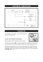
ELECTRICAL CONNECTIONS
INSTALLATION INSTRUCTIONS
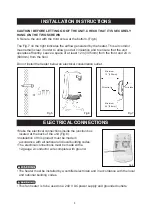
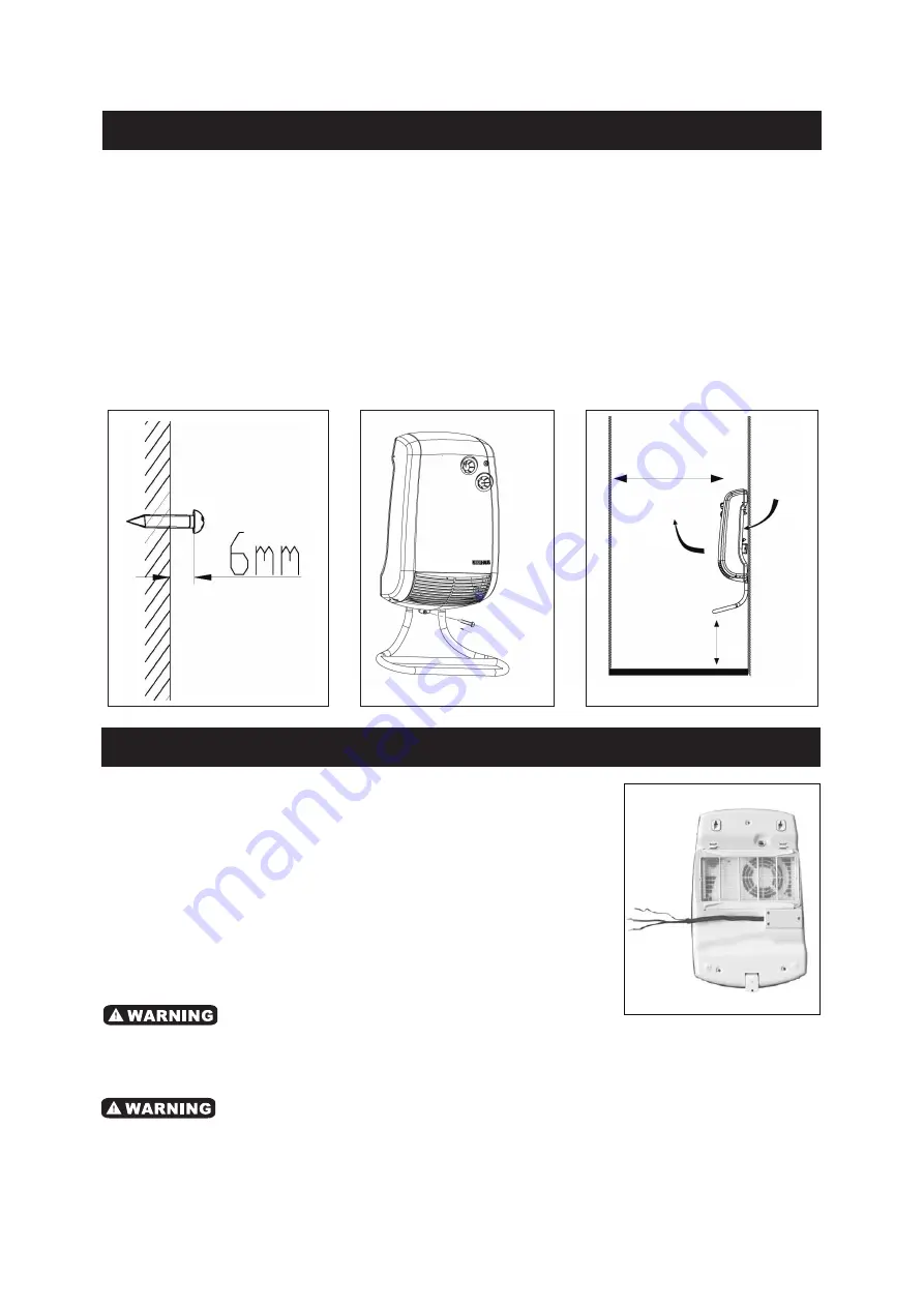
Fig.8
• Make the electrical connections inside the junction box
located at the back of the unit (Fig.8).
• Installation of this product must be made in
accordance with all national and local building codes.
• The electrical connections must be made with a
12-gauge 2-conductor wire complete with ground.
CAUTION! BEFORE LETTING GO OF THE UNIT, CHECK THAT IT IS SECURELY
HUNG ON THE TWO SCREWS
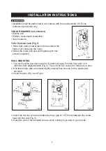
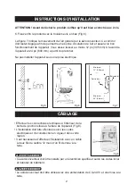
6. Secure the unit with the third screw at the bottom .(Fig.6)
The Fig.7 on the right indicates the airflow generated by the heater. This air corridor
must remain clear in order to allow good air circulation and to ensure that the unit
operates efficently. Leave a space of at least 12 in (305mm) from the front and 24 in
(600mm) from the floor.
Do not install the heater below an electrical convenience outlet.
• The heater must be installed by a certified electrician and in accordance with the local
and national building codes.
• This fan heater is to be used on a 240 V AC power supply and grounded outlets.
Fig.5
Fig.6
Fig.7
Minimum
24” (0.6mm)
Minimum
12” (305mm)
Air outlet
Air intake
Summary of Contents for 68125108
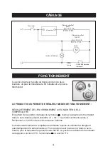
Page 12: ...11 SCHEMATIC DRAWING SCHÉMA ...


