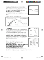
ubbink PoolCleaner Auto Manual Download Page 23

English

Figure 9

IV - Settings  

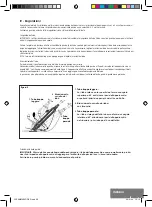
After the installation, switch the pool pump on. Let the pump work for 2 to 3 minutes to make sure all the air is out of the system. 
The hoover must move in the pool with a speed of 2 to 3 meters per minute. Check if all the settings have been done correctly. 

Length of the hose 
IMPORTANT: The filtration must be switched on when checking the length of the hose. The hose will contract when the pump is working 
and it will be longer when the pump is switched off.  

Switch the hoover on and put in on the other end of the pool (it can easily be moved thanks to its telescopic handle.) The hose should be long 
enough to reach the other end of the pool plus one extra meter. Remove the extra sections of hose from the middle part if necessary. The removal of 
the middle part of the hose will prevent the counterweights to be disrupted. Put aside the sections you won’t use immediately. 
NOTE: Switch off the filtration of the pool when adding or removing sections of the hose.

Balancing of the hose 
To have a correct hose balance, switch off the pump and observe the hose. 
The balance of the hose is correct when the suction pad stays flat on the bottom of the pool when switched off and when the hose connection on the 
appliance makes a 45° angle to the bottom as shown in figure 9. The appliance will clean better with correctly balanced counterweights. Move the 
counterweights with 3 cm at a time where necessary, until the correct balance of the hose is obtained. For pools with deep and shallow parts, the 
counterweights need to be adapted in the deep part first and then in the shallow part.

1.  

Hose too light: 

When the hose comes back up and makes an angle of 
more than 45°, the weights need to be put closer to the 
appliance or otherwise the first two weights must be put 
closer together. 

2  

Correct hose balance:

leave as is

3  

Hose too heavy:

When the hose bends from top to bottom and makes an 
angle of less than 45°, the weights need to be put further 
away from the appliance or otherwise the first two weights 
must be separated from each other.


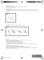
Direction of the water flow:

IMPORTANT: The water flow of your pressure valve can push away the hose of the appliance and influence its 
functioning. This may prevent the appliance from reaching the other end of the pool where the pressure valve 
is located.  Use the water flow guide device to adjust this.

1.  

Hose too light

2.  

Correct hose 

balance

3. 

 Hose

too 

heavy

CLEANMAGIC-DEF.indd   24

26/01/10   10:12

Summary of Contents for PoolCleaner Auto

Page 1: ...CLEANMAGIC DEF indd 2 26 01 10 10 12...

Page 2: ...ASPIRATEUR AUTOMATIQUE CLEANMAGIC DEF indd 3 26 01 10 10 12...

Page 3: ...l appareil et glissez la jusqu son emplacement Pr sentez la c t lisse vers le bas figure 2 Une fois en place la ventouse doit tourner librement tape 2 Ins rez le pare chocs dans l emplacement pr vu si...

Page 4: ...installation est que le r gulateur de pression quilibre automatiquement l coulement de l eau entre le skimmer et l appareil Nous recommandons vivement l utilisation du r gulateur de pression automatiq...

Page 5: ...du tuyau arr ter la pompe et observer le L quilibre du tuyau est correct quand au repos la ventouse reste plat sur le fond de la piscine et le tuyau de raccord sur l appareil fait un angle de 45 par...

Page 6: ...extr mit de la piscine V rifiez la direction du refoulement et r orienter ce dernier selon les besoins V rifiez que le tuyau est assez long pour atteindre l autre extr mit de la piscine V rifiez que l...

Page 7: ...u par des salet s La ventouse n est pas excessivement us e Sinon remplacez la Vous pouvez laisser l appareil dans la piscine except pendant des traitements chimiques Pendant la baignade il est pr f ra...

Page 8: ...AUTOMATISCHER Poolsauger CLEANMAGIC DEF indd 9 26 01 10 10 12...

Page 9: ...r tes das Wort UP finden Dann ist die Saugplatte an ihren Platz aufzuschieben Dabei muss die glatte Seite nach unten weisen siehe Abb 2 Wenn die Saugplatte richtig aufgesetzt ist muss sie sich frei dr...

Page 10: ...immer automatisch ausgleicht Wir empfehlen dringend den automatischen Druckregler zu verwenden um eine sichere und optimale Arbeitsweise zu gew hrleisten Der Regler sorgt automatisch daf r dass das Ge...

Page 11: ...en Der Schlauch ist richtig tariert wenn die Saugplatte im Ruhezustand flach auf dem Boden des Pools liegt und das Anschlussrohr des Ger tes in Bezug auf den Boden einen Winkel von 45 bildet Siehe hie...

Page 12: ...ie die Str mungsrichtung und wechseln Sie sie bei Bedarf berpr fen Sie dass der Schlauch lang genug ist um das andere Ende des Pools zu erreichen berpr fen Sie dass der Schlauch des Ger tes richtig ta...

Page 13: ...verstopft ist die Saugplatte nicht zu sehr verschlissen ist Anderenfalls ist sie zu ersetzen Au er w hrend der chemischen Behandlung k nnen Sie das Ger t stets im Pool belassen W hrend des Badens ist...

Page 14: ...AUTOMATISCHE ZWEMBADZUIGER CLEANMAGIC DEF indd 15 26 01 10 10 12...

Page 15: ...asiselement en schuif de zuignap op zijn plaats met de gladde kant naar onder afbeelding 2 Eenmaal gemonteerd moet de zuignap vrij kunnen draaien Stap 2 Plaats de anti schokring op de juiste plaats aa...

Page 16: ...eel van deze installatie is dat de automatische drukregelaar automatisch de afvoer van het water tussen de skimmer en het apparaat regelt Wij raden het gebruik van de automatische drukregelaar aan voo...

Page 17: ...de pomp uit en bekijk de slang De balans van de slang is goed wanneer de zuignap plat op de bodem van het zwembad blijft wanneer deze niet gebruikt wordt en als de slan gaansluiting op het apparaat e...

Page 18: ...chting van de drukklep en draai deze om indien nodig Controleer of de slang lang genoeg is om de andere kant van het zwembad te bereiken Controleer of de slangbalans goed is Wanneer het apparaat op de...

Page 19: ...or vuil dat de zuignap niet ernstig versleten is anders moet deze vervangen worden Het apparaat kan in het zwembad blijven behalve tijdens chemische behandelingen Als er gezwommen wordt is het beter h...

Page 20: ...AUTOMATIC HOOVER CLEANMAGIC DEF indd 21 26 01 10 10 12...

Page 21: ...y of the appliance and slide the suction pad in place with the smooth surface towards the bottom figure 2 Once assembled the suction pad must be able to turn freely Step 2 Put the anti shock ring on t...

Page 22: ...e regulator automatically balances the water flow between the skimmer and the appliance We recommend the use of the automatic pressure regulator for safety reasons and an optimal functioning The regul...

Page 23: ...he suction pad stays flat on the bottom of the pool when switched off and when the hose connection on the appliance makes a 45 angle to the bottom as shown in figure 9 The appliance will clean better...

Page 24: ...f the pressure valve and turn it if necessary Check if the hose is long enough to reach the other end of the pool Check if the hose balance is correct When the appliance stays on the pool outlet Check...

Page 25: ...he flapper can freely move and that it is not blocked by any dirt The suction pad is not worn out otherwise it needs to be replaced The appliance can stay in the pool except during chemical treatments...

Page 26: ...ASPIRADOR AUTOM TICO CLEANMAGIC DEF indd 27 26 01 10 10 12...

Page 27: ...introd zcala en su emplazamiento Pres ntela con el lado liso hacia abajo figura 2 Una vez en su sitio la ventosa debe poder girar libremente Paso 2 Inserte el parachoques en el emplazamiento previsto...

Page 28: ...l skimmer y el aparato Recomendamos encarecidamente la utilizaci n del regulador autom tico de presi n para una seguridad y una ejecuci n ptimas El regulador se ajusta autom ticamente para suministrar...

Page 29: ...del tubo parar la bomba y observar su estado El equilibrio del tubo es correcto cuando en reposo la ventosa se queda plana en el fondo de la piscina y el tubo de empalme en el aparato forma un ngulo...

Page 30: ...recci n de la descarga y reori ntela seg n sea necesario Verifique que el tubo es lo bastante largo como para alcanzar el otro extremo de la piscina Verifique que el tubo del aparato est bien equilibr...

Page 31: ...libremente y no est obstruido por la suciedad Si la ventosa est excesivamente gastada sustit yala Puede dejar el aparato dentro de la piscina excepto durante los tratamientos qu micos Durante el ba o...

Page 32: ...ASPIRATORE AUTOMATICO CLEANMAGIC DEF indd 33 26 01 10 10 12...

Page 33: ...o dell apparecchio e farla scorrere in posizione Il lato liscio deve essere rivolto verso il basso figura 2 Una volta in posizione la ventosa deve girare liberamente Punto 2 Inserire il paraurti nell...

Page 34: ...l apparecchio Si consiglia vivamente l utilizzo del regolatore di pressione automatico per una maggiore sicurezza e le massime prestazioni Il regolatore si adatta automaticamente per fornire all appa...

Page 35: ...del tubo fermare la pompa e osservarlo Il bilanciamento del tubo corretto quando a riposo la ventosa resta piatta sul fondo della piscina e il tubo di raccordo sull apparecchio crea un angolo di 45 co...

Page 36: ...direzione della mandata e riorientarla secondo necessit Verificare che il tubo sia abbastanza lungo da raggiungere l altra estremit della piscina Verificare che il tubo dell apparecchio sia ben bilan...

Page 37: ...porco La ventosa non sia eccessivamente usurata In caso contrario sostituirla possibile lasciare l apparecchio nella piscina tranne che durante i trattamenti chimici Durante il bagno preferibile scoll...

Page 38: ...de Living Industries Nederland B V Postbus 15 NL 1800 AA Alkmaar Berenkoog 87 NL 1822 BN Alkmaar Tel Sales 31 0 72 5 671 661 Tel 31 0 72 5 671 671 E Mail sales outsideliving com Export Outside Living...

Page 39: ...CLEANMAGIC DEF indd 40 26 01 10 10 12...

Page 40: ...CLEANMAGIC DEF indd 1 26 01 10 10 12...

Reviews: