Page 8
SKU 54461
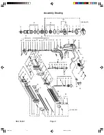
NOTE
: Some parts are listed and shown for illustration purposes only and are not available
individually as replacement parts.
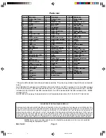
Parts List
Part No. Description
Part No. Description
Part No. Description
1
Cylinder Cap Cover
37
Exhaust Cover
71*
Spring Holder
2*
Screw
38
Muffler
72*
Screw
3*
Exhaust Deflector
39
Magazine Latch
73*
Magazine Support
4*
Air Seal
40
Latch Spring
74*
Nylok Screw
5*
Spring
41
Latch Pin
75*
Magazine Stop
6*
Cylinder Cap
42
Pin Retaner
76*
Fixed Rail
7*
0-ring
43
Safety Pin
77*
Wear Strip
8*
0-ring
44*
Safety Guide Plate
78*
Feeder Spring
9*
0-ring
45*
Safety Pin
79
Mag. Heel Cushion
10*
Firing Valve Piston
46*
Safety Spring
80*
Screw
11*
0-ring
47*
E-ring
81*
Latch Plate
12
Sleeve Retainer
48*
Safety Adjs. Wheel
82*
Moving Rail
13*
Cylinder Sleeve
49*
Upper Safety Element
83*
Spacer
14
Piston Stop
50*
0-ring
84*
Stopper
15
0-ring
51*
Safety Contact Pin
85
Grip
16
Trigger Pin
52*
0-ring
86
Warning Decal
17
Main Body
53*
Main Piston
87*
Screw
18
Driver Bushing
54*
Piston Drv. Coupling
88*
Logo Plate
19
Handle
55*
Inner Spring Pin
89*
Cylinder Cap Assy.
20
0-ring
56*
Outer Spring Pin
90*
Head Vlv. Piston Set
21*
0-ring
57*
Driver Blade
91*
Cylinder Set
22*
Rubber Remote Hsng.
58*
Screw
92*
Trigger Valve Set
23*
Conical Spring
59*
Washer
93*
Trigger Set
24*
0-ring
60*
Safety Cover
94*
Release Catch Assy.
25*
Remote Core
61*
Lower Safety Element
95*
Piston Set
26*
Remote Housing
62*
Front Plate
96*
Screw
27*
0-ring
63*
Spring Pin
97*
Set Screw
28*
Extension Spring Set
64*
Screw
98*
Screw
29*
Trigger Guide
65*
Fixed Backplate
99*
Screw
30*
Pin Bushing
66*
Screw
100*
Cylinder Cap Assy.
31*
Trigger
67*
Screw
101
Duster
32*
Pin
68*
Washer
B0300-070
Cylinder Set
33
Air Inlet 1/4”
69*
Moving Backplate
B11001221
Magazine Set
34
Pin Retainer
70*
Feeder Shoe
35
Screw
36
Serial Label
THE MANUFACTURER AND/OR DISTRIBUTOR HAS PROVIDED THE PARTS DIAGRAM IN THIS MANUAL AS A REFERENCE TOOL
ONLY. NEITHER THE MANUFACTURER NOR DISTRIBUTOR MAKES ANY REPRESENTATION OR WARRANTY OF ANY KIND TO THE
BUYER THAT HE OR SHE IS QUALIFIED TO MAKE ANY REPAIRS TO THE PRODUCT OR THAT HE OR SHE IS QUALIFIED TO
REPLACE ANY PARTS OF THE PRODUCT. IN FACT, THE MANUFACTURER AND/OR DISTRIBUTOR EXPRESSLY STATES THAT ALL
REPAIRS AND PARTS REPLACEMENTS SHOULD BE UNDERTAKEN BY CERTIFIED AND LICENSED TECHNICIANS AND NOT BY
THE BUYER. THE BUYER ASSUMES ALL RISK AND LIABILITY ARISING OUT OF HIS OR HER REPAIRS TO THE ORIGINAL PRODUCT
OR REPLACEMENT PARTS THERETO, OR ARISING OUT OF HIS OR HER INSTALLATION OF REPLACEMENT PARTS THERETO.
PLEASE READ THE FOLLOWING CAREFULLY
* The parts with asterisks cannot be purchased separately. They may be purchased as part of a set as denoted
below:
Set # B0300-070 includes 2,3,4,5,87,89,6,100,7,8,9,10,90,11/ Set #91 includes 9,11,13/ Set #92 includes
21,22,23,24,25,26,27 / Set #93 includes 28,29,30,31,32 / Set #94 includes 44,45,46,47,48,49,50,51 / Set #95
includes 52,53,54,55,56,57/ Set #96 includes 58,59/ Set #97 includes 66,68/ Set #98 includes 67,68/ Set#99
includes 72,59/
Set B11001-221 includes 73,65,64,63,62,61,60,97,66,68,98,63,64,69,84,70,71,74,75,76,77,78,80,81,82
54461.p65
10/10/03, 2:29 PM
8


