


26
103626-04 - 3/18
VIII. SYSTEM START-UP (continued)
2. PRESS RED RESET BUTTON on burner primary
control, hold for one second and release to reset the
control.
3. WATER BOILERS WITHOUT TANKLESS
HEATERS are equipped with an Intelligent Oil
Boiler Control (Cold Start Boiler Control). The
Boiler Control is factory programmed with a High
Limit setpoint of 180°F. The High Limit setpoint is
adjustable between 140°F and 240°F. This tempera-
ture may be varied to suit the installation require-
ments.
HIGH LIMIT DIFFERENTIAL is factory pro-
grammed at 15°F and is adjustable between 10°F
and 30°F.
4. CHECKOUT
Put the system into operation and observe at least
one complete cycle to make sure that the controller
operates properly. See Troubleshooting Section to
use LED to assist in determining system operation.
E.
CHECK / ADJUST OIL BURNER BEFORE
STARTING.
Natural Vent Applications:
1. CHECK BURNER SETTINGS and readjust if
necessary, see Burner Specifications, Tables 5 and 6.
Turn off power to burner before proceeding.
2.
Beckett AFG Burner
This Beckett AFG Burner is equipped with a
non-adjust MB(L1) Fixed Head.
a. Remove Gun Assembly.
b. Verify nozzle size, head size, gun setting, and
positioning of electrodes. This information is
shown in Figure 15, and Beckett AFG Burner
Specifications, Table 5. Replace Gun Assembly.
c. Inspect Beckett head setting on left side of
burner housing by insuring that the witness
mark on the housing and the zero line on the
adjusting plate are aligned, only readjust if
necessary. Refer to Figure 15 and Table 5.
d. Check burner air band and air shutter settings.
Readjust if necessary, see Burner Specifications
Table 5.
e. OPEN ALL SHUT-OFF VALVES in the oil
supply line to the burner.
f. ATTACH A PLASTIC HOSE TO FUEL PUMP
VENT/BLEED FITTING and place the other
hose end into an empty container to catch the oil.
g. SLIGHTLY OPEN FLAME OBSERVATION
PORT COVER on burner swing door, enough to
insert draft gauge probe later.
3.
Riello 40 Series Burner
Use the following procedure to complete the
inspection, check the settings and to change the
nozzle. Refer also to
Model F3 & F5 Installation
Manual, Riello 40 Series Residential Oil Burners
(C6501010).
a. Inspect Riello turbulator setting on left side of
burner by reading the scale embossed on the
housing cover. Refer to Figure 19.
b. Inspect Riello burner air damper and turbulator
setting. Readjust if necessary, see Table 6.
c.
Installation/Removal of Drawer Assembly
,
refer to Figure 16.
i.
Removal:
• Disconnect oil delivery tube nut from
pump.
• Loosen SCREW (3), and then unplug
PRIMARY CONTROL (1) by carefully
pulling it back and then up.
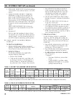
TABLE 5: BECKETT AFG BURNER SPECIFICATIONS
Boiler
Model
Firing Rate
(GPH)
Burner
Model
Nozzle
Settings
Air Gate
Pump Pressure
Turbulator
LE1-L
0.60
F3
Delavan 0.50 x 60°A
2.8
145
0.5
Settings are approximate and must be verified by Smoke and Carbon Dioxide measurement. Readjust where necessary.
TABLE 6: RIELLO 40F BURNER SPECIFICATIONS
Boiler
Model
Firing
Rate
(GPH)
Head
Static
Disc
Nozzle
Settings
Manufacturer GPH
Angle
Type
Air
Shutter
Air
Band
Head
Pump
Pressure
(PSIG)
LE1-L
0.60 *
MB(L1)
3-3/8U
Hago
0.50
70°
B
5
0
Fixed
140
* Low firing rate baffle installed for 0.60 GPH firing rate.
Settings are approximate and must be verified by Smoke and Carbon Dioxide measurement. Readjust where necessary.