U.S. Boiler Company LE Series Installation, Operating And Service Instructions Download Page 13

13

 103626-04 - 3/18

IV.  WATER PIPING AND TRIM

WARNING

Failure to properly pipe boiler may result in improper operation and damage to boiler or structure.
Oxygen contamination of boiler water will cause corrosion of iron and steel boiler components, and 

can lead to boiler failure.  U.S. Boiler Company’s Warranty does not cover problems caused by oxygen 

contamination of boiler water or scale (lime) build-up caused by frequent addition of water.

 A.

  DESIGN  A  PIPING  SYSTEM and install boiler 

which will prevent oxygen contamination of boiler 

water and frequent water additions.
1.  There are many possible causes of oxygen contami-

nation such as:
a.   Addition of excessive make-up water as a result 

of system leaks.

b.  Absorption through open tanks and fittings.

c.   Oxygen permeable materials in the distribution 

system.

 2. In order to insure long product life, oxygen sources 

should be eliminated.  This can be accomplished by 

taking the following measures:
a.   Repairing system leaks to eliminate the need for 

addition of make-up water.

b.  Eliminating open tanks from the system.

c.   Eliminating and/or repairing fittings which allow 

oxygen absorption.

d.  Use of non-permeable materials in the distribu-

tion system.

e.   Isolating the boiler from the system water by 

installing a heat exchanger. 

3.  Connect System supply and return piping to boiler.  

See Figures 8A and 8B.  Also, consult I=B=R, 

"Residential Hydronic Heating Installation and 

Design Guide".  Maintain minimum ½ inch clear-

ance from hot water piping to combustible materials.

WARNING

System supply and return piping must be 

connected to correct boiler pipe.
U.S. Boiler Company recommends sizing 

the system circulator to supply sufficient 

flow (GPM) to allow a 20°F temperature 

differential in the system.  When sizing the 

system circulator, the pressure drop of all 

radiators, baseboard and radiant tubing and 

all connecting piping must be considered.

a.   Use a system bypass if the boiler is to be 

operated in a system which has a large volume or 

excessive radiation where low boiler water 

temperatures may be encountered (i.e. converted 

gravity circulation system, etc.) The bypass 

should be the same size as  the supply and return 

lines with valves located in the bypass and return 

line as illustrated in Figures 8A and 8B in order 

to regulate water flow for maintenance of higher 

boiler water temperature.  

  Set the bypass and return valves to a half throttle 

position to start.  Operate boiler until the system 

water temperature reaches its normal operating 

range. 

  Adjust the valves to maintain 180°F to 200°F 

boiler water temperature and greater the 120°F 

return temperature.  Adjust both valves simulta-

neously.  Closing the boiler return valve while 

opening the bypass valve will raise the boiler 

return temperature.  Opening the boiler return 

valve while closing the by-pass valve will lower 

the boiler return temperature.

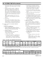
b.  If this boiler is used in connection with refrigera-

tion systems, the boiler must be installed so that 

the chilled medium is piped in parallel with the 

heating boiler using appropriate valves to 

prevent the chilled medium from entering the 

boiler.  See Figure 7.  Also, consult I=B=R, 

"Residential Hydronic Heating Installation and 

Design Guide".

c.   If this boiler is connected to heating coils located 

in air handling units where they may be exposed 

to refrigerated air, the boiler piping must be 

equipped with flow control valves to prevent 

Figure 7:  Recommended Piping for Combination 

Heating and Cooling (Refrigeration) System

Summary of Contents for LE Series

Page 1: ...OIL FIRED BOILER For service or repairs to boiler call your heating contractor When seeking information on boiler provide Boiler MOdel Number and Serial Number as shown on Rating Label Boiler Model N...

Page 2: ...safety devices D All wiring on boilers installed in the USA shall be made in accordance with the National Electrical Code and or Local Regulations DANGER Indicates an imminently hazardous situation w...

Page 3: ...or to see that all controls are correctly installed and are operating properly when installation is complete including verifying that the limit sensor is fully installed seated in bottom of Well Failu...

Page 4: ...ed before the start of the heating season for any obstructions A clean and unobstructed chimney flue is necessary to allow noxious fumes that could cause injury or loss of life to vent safely and will...

Page 5: ...5 103626 04 3 18 I GENERAL INFORMATION Figure 1A LE Packaged Water Boiler with Beckett AFG Burner...

Page 6: ...6 103626 04 3 18 I GENERAL INFORMATION continued Figure 1B LE Packaged Water Boiler with Riello 40F Burner...

Page 7: ...INFORMATION Boiler Model Water Capacity Gallons Approximate Shipping Weight LBS Minimum Chimney Requirements Round In Dia Rectangle In x In Height Ft LE1L 6 1 325 6 8 x 8 15 Notes 1 MBH refers to tho...

Page 8: ...erican National Standard NFPA 31 Standard for the Installation of Oil Burning Equipment NOTE 2 LE Series boilers can be installed in rooms with clearances from combustible material as listed above Lis...

Page 9: ...unconfined space of a conven tionally constructed building the fresh air infiltration through cracks around windows and doors normally provides adequate air for combustion and ventilation 5 For boile...

Page 10: ...hing holes in Spacer Tubesheet or Door See Figure 4 Tighten all hex nuts and cap screws by hand only 7 Replace door assembly Hinge brackets attached to door must rest on top of hinge brackets attached...

Page 11: ...on front of L7248L Control Mount Control on factory installed immersion well located in center tapping on top of boiler with L7248L Boiler Control Transformer Relay Control Center Harness Assembly on...

Page 12: ...12 103626 04 3 18 Figure 5B Relief Valve and Boiler Control Assembly Details Riello 40F Burner Figure 6 Limit Sensor Insertion III PACKAGED BOILER ASSEMBLY TRIM AND CONTROLS continued...

Page 13: ...circulator to supply sufficient flow GPM to allow a 20 F temperature differential in the system When sizing the system circulator the pressure drop of all radiators baseboard and radiant tubing and a...

Page 14: ...14 103626 04 3 18 IV WATER PIPING AND TRIM continued Figure 8A Recommended Water Piping for Circulator Zoned Heating Systems Supply Side Circulator...

Page 15: ...15 103626 04 3 18 IV WATER PIPING AND TRIM continued Figure 8B Recommended Water Piping for Zone Valve Zoned Heating Systems Supply Side Circulator...

Page 16: ...G Installation is NOT complete unless a safety relief valve is installed as shown in Figure 8A or 8B Safety relief valve discharge piping must be piped near floor to eliminate potential of severe burn...

Page 17: ...e burned and sends less heat up the chimney A new boiler probably has a higher efficiency than the boiler being replaced That probably means that the stack temperature from the new boiler will be lowe...

Page 18: ...18 103626 04 3 18 V VENTING continued Figure 9 Recommended Smoke Pipe Arrangement and Chimney Requirements Figure 10 Draft Regulator Locations...

Page 19: ...er jacket junction boxes and or control boxes 3 Use armored cable BX over all exposed line voltage wiring 4 If an indirect water heater is used use priority zoning DO NOT use priority zoning for Hydro...

Page 20: ...4 3 18 VI ELECTRICAL continued Figure 11A Schematic Wiring Diagram Cold Start Control with Beckett AFG Burner REFER TO FIGURE 12 FOR SCHEMATIC WIRING DIAGRAM OF APPROPRIATE BURNER AND OIL PRIMARY CONT...

Page 21: ...3 18 VI ELECTRICAL continued Figure 11B Schematic Wiring Diagram Cold Start Control with Riello 40 Series Burner REFER TO FIGURE 12 FOR SCHEMATIC WIRING DIAGRAM OF APPROPRIATE BURNER AND OIL PRIMARY C...

Page 22: ...PRIATE STEAM OR WATER BOILER CONTROL SCHEMATIC REFER TO FIGURES 11A AND 11B NOTE APPLY THIS BURNER SCHEMATIC TO APPROPRIATE STEAM OR WATER BOILER CONTROL SCHEMATIC REFER TO FIGURES 11A AND 11B Figure...

Page 23: ...pression fittings 4 Use of a high efficiency micron filter Garber or equivalent in addition to conventional filter is highly recommended B SINGLE PIPE OIL LINES 1 Standard burners are provided with si...

Page 24: ...0 31 100 11 26 100 12 21 83 13 62 14 41 Lift H See Figure Maximum Length of Tubing H R See Figure 3 8 OD Tubing 3 GPH 1 2 OD Tubing 3 GPH 0 93 100 2 85 100 4 77 100 6 69 100 8 60 100 10 52 100 12 44 1...

Page 25: ...d expansion tank g Allow water to overflow from bucket until discharge from hose is bubble free for 30 seconds h When zone valve is completely purged of air close zone valve or shut off valve Open zon...

Page 26: ...air band and air shutter settings Readjust if necessary see Burner Specifications Table 5 e OPEN ALL SHUT OFF VALVES in the oil supply line to the burner f ATTACH A PLASTIC HOSE TO FUEL PUMP VENT BLEE...

Page 27: ...PTER 2 from the DRAWER ASSEMBLY by loosening the SCREW 1 ii Remove existing nozzle from nozzle adapter iii Insert the proper NOZZLE into NOZZLE ADAPTER and tighten securely DO NOT cover tighten refer...

Page 28: ...sure was factory pre set but must be checked at time of burner start up A pressure gauge is attached to the PRESSURE BLEEDER PORT 7 for pressure readings Two PIPE CONNECTORS 4 are supplied with the bu...

Page 29: ...L BURNER WHILE OPERATING flame present 1 ADJUST DRAFT REGULATOR for a draft of zero to maximum of 03 water gauge in the breeching after chimney has reached operating temperature and while burner is ru...

Page 30: ...cycling the burner operation about 5 to 10 times will rid oil line of this air 2 IF NOZZLE CONTINUES TO DRIP repeat Paragraph H Step 1 above If this does not stop the dripping remove cut off valve an...

Page 31: ...ugged from the control and the resistance measured with a meter in the conventional way Conduct these tests with flame present see chart below Flame Detection Range Normal 0 1600 ohms Limited 1600 ohm...

Page 32: ...mit setting The burner should shut down and circulators continue running c Allow the temperature to drop below control setting The burner must restart d Boiler installation is not considered complete...

Page 33: ...Orientation c When the thermostat calls for heat the boiler control starts the system circulator and the thermal purge circulator pre purge time begins If the time is completed or boiler temperature i...

Page 34: ..._ The Boiler Control is factory programmed with a High Limit Setpoint of 180 F The boiler turns off when the boiler water temperature bt is above this value The High Limit setpoint is adjustable betwe...

Page 35: ...n 140 Start with no delay TT on 140 Start after 2 minute delay ZR on ZC_ ZR 140 Start with no delay ZR on ZC_ ZR 140 Start after 2 minute delay ZR on ZC_ DH 140 Start with no delay ZR on ZC_ DH 140 St...

Page 36: ...ses a call for heat and energizes the System Circulator output to service heating zone 1 A second zone s thermostat may be wired to the ZR input to energize heating zone 2 circulator wired to the ZC o...

Page 37: ...leaned and refilled as previously described test the pH of the water in the system This can easily be done by drawing a small sample of boiler water and testing with hydrion paper which is used in the...

Page 38: ...all corners 3 Always keep the manual fuel supply valve shut off if the burner is shut down for an extended period of time 4 To recondition the heating system in the fall season after a prolonged shut...

Page 39: ...sary BE CAREFUL not to damage liner or rear door insulation piece Inspect front and rear door insulation pieces front door gaskets and combustion chamber liner for damage Replace any damaged pieces im...

Page 40: ...iler is connected to a dirty or inadequate chimney The interior of the chimney flue must be inspected and cleaned before the start of the heating season and should be inspected periodically throughout...

Page 41: ...rator 2 Long sleeved loose fitting clothing 3 Gloves 4 Eye Protection Take steps to assure adequate ventilation Wash all exposed body areas gently with soap and water after contact Wash work clothes s...

Page 42: ...oor spray pattern from the nozzle The smaller the firing rate the smaller the slots become in the nozzle and the more prone to plugging it becomes with the same amount of dirt 6 WATER Water in the fue...

Page 43: ...ablished within 15 seconds of oil valve actuation known as Trial For Ignition TFI lockout will occur Lockout is indicated by a red LED solid on located on the oil primary control Hard Lockout will occ...

Page 44: ...ered during safety output relay check sequence or un powered during running or powered in idle in combination with water temperature above 264 F limit Cycle power to the control Replace control if pro...

Page 45: ...oiler Company Wholesale distributor Should you require assistance in locating a U S Boiler Company Distributor in your area or have questions regarding the availability of U S Boiler Company products...

Page 46: ...46 103626 04 3 18 XIII REPAIR PARTS continued Figure 27 LE Bare Boiler Assembly...

Page 47: ...ded in 108137 01 4E Front Door and Furnace Rope Gasket 1 Included in 108137 01 4F 6 x 3 4 Drive Screw 2 80860718 5A Hinge Bracket 4 7022701 5B Hinge Spacer 2 7303310 5C Hinge Pin 2 80861614 5D Hairpin...

Page 48: ...48 103626 04 3 18 XIII REPAIR PARTS continued Figure 28 LE Boiler Jacket Insulation...

Page 49: ...R8239A1052 Control Center Transformer Relay Required on Riello Burner Applications Only 1 80160235 2 Honeywell 123871A 3 4 NPT x 3 1 80160452 3 Conbraco 10 408 05 3 4 FPT 30 PSI Relief Valve 1 816603...

Page 50: ...ENT OIL BURNER PARTS CONTACT YOUR WHOLESALER OR THE BURNER MANUFACTURER R W BECKETT CORP 38251 CENTER RIDGE RD P O BOX 1289 ELYRIA OHIO 1 800 645 2876 44036 XIII REPAIR PARTS continued FIGURE 30 BECKE...

Page 51: ...w Firing Rate Baffle Kit 5880 Spline Nut Bulkhead 3666 Connector Tube Assembly 5394 Electrode Clamp 149 Electrode Clamp Screw 4219 Electrode Insulator Assembly Kit 5780 Nozzle Line LT Assembly Less He...

Page 52: ...l Burners C6501010 for an exploded view of the burner and a list of spare parts Riello Corporation of America 35 Pond Park Road Hingham Massachusetts 02043 Telephone 617 749 8292 Facsimile 617 740 206...

Page 53: ...sed to connect the probe LWCO to the supply or return piping as shown below Select the appropriate size tee using the LWCO manufacturer s instructions Often the branch connection must have a minimum d...

Page 54: ...y be used if the boiler manufacturer has provided piping and wiring connections and instructions to allow for this application How to Test Shut off fuel supply Lower water level until water level is B...

Page 55: ...y Side Circulator Section V Venting Figure 9 18 Recommended Smoke Pipe Arrangement and Chimney Requirements Figure 10 18 Draft Regulator Locations Section VI Electrical Figure 11A 20 Schematic Wiring...

Page 56: ...on Chamber Section XIII Repair Parts Figure 27 46 LE Bare Boiler Assembly Figure 28 48 LE Boiler Jacket Insulation Figure 29 49 LE Boiler Trim Controls Figure 30 50 Beckett AFG Oil Burner Repair Parts...

Page 57: ...cations Table 6 26 Riello 40F Burner Specifications Section IX Operating Table 7 33 Sequence of Operation Table 8 35 Circulator Pre purge Time Example Parameter PP_ 2 Minutes Table 9 35 Domestic Hot W...

Page 58: ...58 103626 04 3 18...

Page 59: ...59 103626 04 3 18...

Page 60: ...60 103626 04 3 18 U S Boiler Company Inc P O Box 3020 Lancaster PA 17604 1 888 432 8887 www usboiler net...

Reviews: