background image

IQ LCD Display Kit – Instruction Sheet 

105918-01 


Page 4 of 12 

USER INTERFACE 

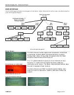
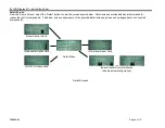
The IQ LCD Display’s screens are arranged as shown below.  Basic information for each screen is provided below the 
general arrangement diagram:


Home

Overview

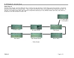
Status

Bargraphs

Trend

Screens

Warning 

Screen

Screen Arrangement 

Overview

Reset Card 

Adjust Screens

IQ Control 

Adjust Screens

Status

Button

Help

Button

Adjust

Button

Adjust

Menu

Contractor

Contact Info

Troubleshooting

Menu

Alarm

Menu

Alarm Detail

Screens

Help

Menu

Alarm History

Screens

Troubleshooting

Screens

Contractor

Contact Info

Log into

Adjust mode

Additional Information “i” 

Screens are available 

from most screens

Detail

Button

IQ Zone 

Panel

IQ LWCO 

Option Card

Boiler 

Control

Detail
Menu

IQ Aquastat

Option Card

IQ Outdoor 

Reset Card


Screen General Arrangement 

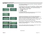
Home Screen


The Home Screen provides supply water temperature, central heat 
and domestic hot water (DHW) heat demand status, as well as 
“Energy Save” status.  Energy Save On appears when the Reset 
Setpoint is reduced below the HL Setpoint.   
 

The


“ 

” symbol indicates the presence of an information screen.  

Press the 


“ 

” button and view helpful information related to 

information on this screen.  The Status, Help and Adjust buttons allow 
the user to navigate to these functions. 
 
The Home Screen turns “RED” and the Help button flashes when 
there is an alarm or the boiler is unable to start when a demand is 
present. 


Home Screen in “alarm state” 


(Screen shows faulted sensor) 
 

Typical Information Screen 


Summary of Contents for 105917-01

Page 1: ...ols This product is compatible with the IQ Option Cards and the Wireless Outdoor Air Reset Adaptor P N 105121 01 and IQ Zone Control Circulator Panel P N 104590 01 GENERAL The Portable Diagnostic Disp...

Page 2: ...ian 3 After installation is complete check out product operation as provided in these instructions Caution Electrical Hazard Disconnect power before beginning installation and wiring Failure to do so...

Page 3: ...panel on most boilers See connections for different boilers below 4 Turn Power On Boilers Connection Example ES2 Boiler Series 3 Boiler ESC Boiler MPO IQ Oil Boiler Series 2 PVG V8H LEDV1 LE1 RSAH RSA...

Page 4: ...most screens Detail Button IQ Zone Panel IQ LWCO Option Card Boiler Control Detail Menu IQ Aquastat Option Card IQ Outdoor Reset Card Screen General Arrangement Home Screen The Home Screen provides s...

Page 5: ...other boiler monitored status These screens read information from all connected IQ Control System components For example the bar graph screen shown below shows air temperature measured by an EnviraCOM...

Page 6: ...screens provide additional information for connected control components The below screens show some of the possible detail screens screens show dependent on connected components Boiler Control Limits...

Page 7: ...irected to the service company that installed or serviced the display Using Adjustment mode as described below a contractor can insert their own contact information on these screens Trouble Shooting I...

Page 8: ...component to adjust by simply selecting the item Typical Adjustment Screen Typical Information Screen The technician can simply use the up or down arrow keys to make an adjustment to the control syste...
Page 9: ...on Silver Bezel with Gateway Wire Harnesses Portable Assembly Carrying Case Logo Plates and Instructions 105913 01 IQ LCD Display Boiler Exterior Mounted STN Monochrome White Red backlight 5Vdc Power...

Page 10: ...IQ LCD Display Kit Instruction Sheet 105918 01 Page 10 of 12...

Page 11: ...IQ LCD Display Kit Instruction Sheet 105918 01 Page 11 of 12 This page intentionally left blank...

Page 12: ...IQ LCD Display Kit Instruction Sheet 105918 01 Page 12 of 12 U S Boiler Company Inc P O Box 3020 Lancaster PA 17604 1 800 432 8887 www usboiler net...

Reviews: