background image


http://u-prox.com 

10


Assignment of the access control panel contacts 
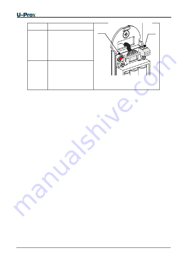
Name


Assignment


Fig. 2

. U-Prox IP500 Smart Handle 

back board


DC 

Door Contact for door 

position supervision 

FactSet 

Return to factory 

setting button 

Sound and light panel indication is on reader light emitting diode (LED) of reader 

Siren  sound  and  LED  blinks  reds  on  identifier  presentation


–  low  battery, 

replace 

Long beep and LED lights red constantly


– access denied 

Short beep and LED lights green constantly


– access granted 

One beep and LED alters green and yellow light


– free pass mode 

One beep and LED blinks red


– door blocked mode 

Three beeps and LED blinks red


– panel download in progress 

Tapping sound signals 

- within range of infrared sensor entered obstacle. 

Siren  sound  and  LED  blinks  reds  sounds

  -  within  range  of  the  infrared  sensor 

obstacle  is  more  than  a  minute.  Control  panel  also  sent  event  "Reader  sensor 
trouble" 

Panel operation 

The panels supplied unloaded with factory settings below in document. To make the 
panel  work  in  access  control system  (ACS)  you  have  to  add  it  to  the  system  using 
the  automatic  adjustment  mode  or  manually  and  download  the  program  settings 
from U-Prox Software. 

P

anel goes to mode “Normal” after  downloading program settings if door contact is 

in normal state. Panel can supervise one access point with request-to exit operated 
with  inner  door  handle.  There  are  four  different  modes  of  access  point:  "Normal", 
"Alarm",  "Blocking"  and  "Free  pass".  Mode  "Free  pass"  has  the  highest  priority,  as 
this mode is activated in the event of a fire, followed by modes of "Blocking", "Alarm" 
and "Normal" in decreasing order of priority. 

"Normal" mode 

This  is  the  main  mode  of  panel.  In  this  mode  the  panel  grants  or  denies  access  to 
RF ID owners.  

FactSet 

DC 

Summary of Contents for IP500

Page 1: ...1 006 Wireless access control panel U Prox IP500 Smart Handle Installation and programming manual...

Page 2: ...the panel the pins and the mode of work are described in the Description section Order of installation adjustment of external devices and panel configuration are described in Working with the device s...

Page 3: ...1 Free Pass Mode 11 Blocking mode 12 RF ID properties cards 12 The communicator 12 Wireless lock system architecture 14 Wireless lock system deployment 15 Server addresses automatic configuration for...

Page 4: ...input for door position supervision The panel can work offline or as part of the network To add it to access control network U Prox IC L control panel used U Prox IC L panel communicates with U Prox...

Page 5: ...927 5 MHz o Guaranteed range 6 20 m o U Prox HE and U Prox HW repeaters for range extension Door contact input Request to exit on inner door handle Adjusted with U Prox IP software Real time clock No...

Page 6: ...d control has two passageways and the door having single sided reader only one passageway Access point which consists of two passageways is called double sided and the point of access which consists o...

Page 7: ...ss are indicated when setting user access rights Depending on modification control panel stores up to 250 time zones 250 week schedules can be combined from these time zones Moreover control panel can...

Page 8: ...utcheon 2 RF ID reader 3 Light emitting diode 4 Card presence Detector 5 Locking Cylinder 6 Outer handle 7 Door contact optional 8 Mortise lock 9 Cover plate 10 Inner escutcheon 11 Inner handle Fig 1a...

Page 9: ...diode 4 Card presence Detector 5 Locking Cylinder 6 Outer handle 7 Door contact optional 8 Mortise lock 9 Cover plate 10 Inner escutcheon 11 Inner handle Fig 1 U Prox IP500 panel installed on the door...

Page 10: ...sounds within range of the infrared sensor obstacle is more than a minute Control panel also sent event Reader sensor trouble Panel operation The panels supplied unloaded with factory settings below...

Page 11: ...count is exhausted for the temporary card visitor Alarm Mode Depending on the programmed functions Access point goes into mode Alarm in case of unauthorized passage Door Forced Open opening of panel...

Page 12: ...ters event Alarm cancelled and puts the door to Normal mode If the card that has no right to cancel the Alarm is passed the door will remain in the same state Access denied Alarm Status event recorded...

Page 13: ...est signals repeated every 2 minutes Attention The delay of delivery of the operator command to U Prox IP500 Smart Handle may last up to 2 minutes i e the period of the test signal Panel provides encr...

Page 14: ...i e make decision about the access using data uploaded beforehand U Prox IC L control panel routes data from the allowed U Prox IP500 Smart Handle wireless panels via U Prox HE and U Prox HW repeaters...

Page 15: ...cols DHCP for instance allowed to provide the plug and play principle The mode of the automatic server address configuration in the panels eases the wireless lock system deployment significantly The d...

Page 16: ...access control system server about itself as a new device in the local network Despite it is broadcast announcement it is limited with one range local network and active network equipment That s why t...

Page 17: ...the local network Despite it is broadcast announcement it is limited with one range local network and active network equipment That s why the IP addresses of the U Prox IC L panel are to be set manual...

Page 18: ...tem database e Operator must upload U Prox IC L control panel after the U Prox IP500 Smart Handle panel added to the DB f Operator must upload U Prox IP500 Smart Handle panel after the adjustment it i...

Page 19: ...tcheon 2 Reader 3 Connection cable 4 Panel board 5 Door contact magnetic optional 6 Mortise lock and cover plate screws 7 Mortise lock 8 Cover plate 9 Cylinder retainer pin 10 Rectangle 11 Inner escut...

Page 20: ...n 2 Reader 3 Connection cable 4 Panel board 5 Door contact magnetic optional 6 Mortise lock and cover plate screws 7 Mortise lock 8 Cover plate 9 Cylinder retainer pin 10 Rectangle spindle 11 Inner es...

Page 21: ...ange handles position for installation on desired door side proceed A Outer escutcheon See Fig 9 1 Release stopper rotating it on 900 2 Alter handle position 3 Return stopper to initial position B Inn...

Page 22: ...10 fell into corresponding holes in the mortise lock and outer escutcheon precisely 10 Fix inner 11 and outer 1 escutcheons with screws 13 11 Insert the cylinder 16 if used and secure it with cylinde...

Page 23: ...prox com 23 Fig 10a Cable running model for Lockwood 3582 Mortise Lock 89 9 mm Fig 10b Cable running model for Lockwood 3572 Mortise Lock 64 mm Opening for cables and DC wire Opening for cables and D...

Page 24: ...ss point states without the door contact proper operation Panel generates the Entry occurred message on inner handle press when the door contact is absent To enable door contact set the Z1 zone as A d...

Page 25: ...Fig 13 Battery replacement Return to factory settings To Return to factory settings 1 De power control panel remove at least one battery 2 Press and hold FactSet button 3 Supply power to control panel...

Reviews: