


USER GUIDE
Troubleshooting 1
u-line.com
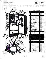
SAFETY • INSTALLATION & INTEGRATION • OPERATING INSTRUCTIONS • MAINTENANCE •
SERVICE
Troubleshooting
BEFORE CALLING FOR SERVICE
If you think your U-Line product is malfunctioning, read
the CONTROL OPERATION section to clearly understand
the function of the control.
If the problem persists, read the NORMAL OPERATING
SOUNDS and TROUBLESHOOTING GUIDE sections below
to help you quickly identify common problems and
possible causes and remedies. Most often, this will resolve
the problem without the need to call for service.
IF SERVICE IS REQUIRED
If you do not understand a troubleshooting remedy, or
your product needs service, contact U-Line Corporation
directly at +
1.414.354.0300
.
When you call, you will need your product Model and
Serial Numbers. This information appears on the Model
and Serial number plate located on the upper right or rear
wall of the interior of your product.
NORMAL OPERATING SOUNDS
All models incorporate rigid foam insulated cabinets to
provide high thermal efficiency and maximum sound
reduction for its internal working components. Despite this
technology, your model may make sounds that are
unfamiliar.
Normal operating sounds may be more noticeable because
of the unit’s environment. Hard surfaces such as cabinets,
wood, vinyl or tiled floors and paneled walls have a
tendency to reflect normal appliance operating noises.
Listed below are common refrigeration components with a
brief description of the normal operating sounds they
make. NOTE: Your product may not contain all the
components listed.
• Compressor: The compressor makes a hum or pulsing
sound that may be heard when it operates.
• Evaporator: Refrigerant flowing through an evaporator
may sound like boiling liquid.
• Condenser Fan: Air moving through a condenser may
be heard.
• Running Water: As your unit continues to produce ice
you will hear water flowing into the collection chambers
and running over the evaporator.
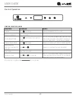
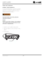
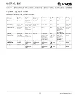
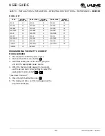
TROUBLESHOOTING GUIDE
DANGER
!
ELECTROCUTION HAZARD. Never attempt to
repair or perform maintenance on the unit
before disconnecting the main electrical power.
Troubleshooting - What to check when problems occur:
Problem
Possible Cause and Remedy
Unit Does Not
Operate.
Electronic
Display Blank.
No electrical supply. Plug unit in or check
circuit breaker.
Display
Showing Error
Code.
If display shows error 10E or ER, check to
make sure door is sealing correctly. Make sure
to close door completely. If sealing the door
does not clear the error, contact U-Line service
for more information.
Unit Develops
Condensation
on External
Surfaces.
The unit is exposed to excessive humidity.
Moisture will dissipate as humidity levels
decrease.
Poor Ice
Quality.
Unit may not be level. Check if unit is level.
Ice maker system may be dirty. Clean the ice
maker.
No Ice
Production.
Ensure water is being supplied to the unit.
Verify the ice making unit is turned on.
Not Enough
Ice.
Ensure the condenser coil is clean and free of
any dirt or lint build-up.
Water in Ice
Bin.
Drain may be restricted, ensure drain is free of
foreign debris.
29


