background image

8 Door Panel Installation

12

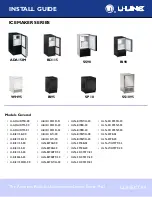
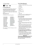
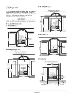
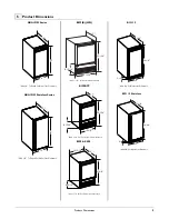
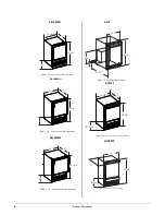
U-Line Product Features

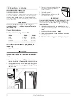
Door Panel Preparation

BI-95, BI-2115B(WH), WH95BTP

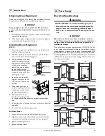
A custom door panel may be inserted into the doorframe. Custom 
door panels can be flat or raised, as long as the maximum panel 
thickness, where inserted into the door reveal (channel), is no 
more than 1/4" thick. For raised panels, the depth of the reveal is 
1/4" on all four sides.

IMPORTANT

IMPORTANT

Raised panels will reduce the door’s 90° swing/zero 
clearance if the unit is installed next to a wall or similar 
type of structure.

Panel Dimensions.

The door panel must not weigh more than 20 lbs.

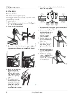
Door Panel Installation (98, SP18, & 

ADA15)

Install the insert as follows:

CAUTION

Use care when handling the insert. Insert edges may be 
sharp.

1. Remove top hinge screw pin with Phillips head screwdriver. 

Remove door by tilting forward and lifting off bottom hinge pin.

2. Pull door gasket out of groove (top edge of door only). Start in 

the middle and pull outward, moving toward the edge. This may 
take some force.

Model

Width

Height

BI-95

12 15/16"

13 15/32"

BI-2115

14 1/32"

27 11/16"

BI95BTP

12 15/16"

13 15/32"

BI-95
BI-2115

BI95BTP

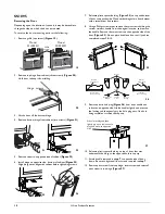
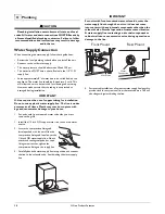
3. Remove the two outside screws holding 

door handle. Slightly separate door 
handle from door.

4. Pull handle up and off.

5. Slide custom door panel insert into 1/4-

inch channel in door front.

IMPORTANT

IMPORTANT

Some units include a magnet on the bottom of the door. 
Use care not to damage magnet, when installing door 
insert. Do not set door on bottom edge when pushing 
insert into place.

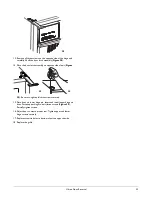
6. Holding door gasket out of the way, replace handle on door, 

making sure it is seated properly on insert and that screw holes 
line up.

7. Install two small screws removed in 

Step 3

.

8. Starting at the corners and working inward, push door gasket 

into place on door.

9. Place door on bottom hinge pin and install upper hinge screw.

Summary of Contents for U-ADA15IMB-00

Page 1: ...SOD 20 ULN BI98B 00 ULN SS1095NF 03 U ADA15IMS 01 U BI2115SOD 22 ULN BI98B 20 ULN SS1095NF 20 U BI2115B 00 U BI2115W 00 ULN BI98WH 00 ULN SS98 03 U BI2115B 20 U BI2115W 20 ULN BI98WH 20 ULN SS98 20 U...

Page 2: ...5 95TP BCM95 BI98 BI2115 5 SS1095 SP18 BCM95 WH95 SS1095NF 6 Door Swing Dimensions 7 Other Site Requirements Power Supply 7 Water Supply 7 Environmental Requirements 7 Door Reversal BI95 BI98 8 WH95TP...

Page 3: ...HAZARD Electrical Grounding Required Never attempt to repair or perform maintenance on the unit until the electricity has been disconnected Never remove the round grounding prong from the plug and ne...

Page 4: ...o WATERHOOKUP Exterior Cleaning Black and White Models Black and White surfaces may be cleaned with a mild detergent and warm water solution Do not use solvent based or abrasive cleaners Use a soft sp...

Page 5: ...U Line May Be Added Above or Below Unit to Enclose for a Built In Look 14 3 16 18 1 2 Minimum See Electrical Specifications for Power Supply Models BI 98 SS 98 Models BI 2115 Models SP 18 Models 8 Typ...

Page 6: ...or 14 1 4 Cut Out Width 3 4 Minimum Flange Mounting Area 3 4 Minimum Flange Mounting Area Cut Out Height 26 1 16 Filler Panel Not Provided by U Line Needed to Attach Mounting Flange on Unit 18 1 2 Min...

Page 7: ...ne Clearance 15 34 1 8 3 13 16 23 1 8 BI2115 Stainless Add 1 1 2 For Water Line Clearance 25 1 16 13 15 16 17 8 15 16 BI95BTP BI98 SS98 27 3 8 14 15 16 20 Add 1 1 2 For For Water Line Clearance 8 15 1...

Page 8: ...rance 17 25 1 8 15 1 8 9 Add 1 1 2 For Water Line Clearance 25 1 16 14 17 9 15 1 8 24 1 2 18 7 8 7 9 16 1 2 Add 1 1 2 ForWater Line Clearance BCM95 WH95TP 17 25 1 8 14 8 15 16 Add 1 1 2 For For Water...

Page 9: ...r those models with ice makers If the ambient temperature is expected to drop below 45 F 7 C drain all water from the unit to prevent freezing damage which is not covered by the warranty For best perf...

Page 10: ...posite side and place door on bottom hinge pin See Figure 5 Clean out bushing hole in door bottom with a screwdriver if necessary 6 Remove plastic hole plug from door handle and relocate on opposite s...

Page 11: ...ce door on bottom hinge pin See Figure 14 Clean out bushing hole in door bottom with a screwdriver if necessary 7 Remove plastic travel pin from door handle and relocate on opposite side See Figure 15...

Page 12: ...handle from the original location and remove the handle Remove the two screws on the opposite side of the door Figure 25 Do not place handle on door until you have completed steps 9 10 9 Remove plasti...

Page 13: ...de of unit Figure 29 Be sure to tighten all three screws securely 15 Place door on lower hinge pin Invert and install upper hinge on door Fasten upper hinge to unit three screws Figure 30 Partially ti...

Page 14: ...ing forward and lifting off bottom hinge pin 2 Pull door gasket out of groove top edge of door only Start in the middle and pull outward moving toward the edge This may take some force Model Width Hei...

Page 15: ...ide of the door Adjusting Door Alignment BI 2115 1 Remove top hinge screw pin Remove door by tilting forward and lifting off bottom hinge pin 2 With door upside down loosen but do not remove the two s...

Page 16: ...tic may crack or rupture with age and cause water damage to your home 1 For units with front mounted water solenoids you must remove the grille 1 Install the 1 4 inch OD copper water line to the main...

Page 17: ...lation 1 Open the water supply valve in the main water source 2 Plug in the powercord 3 Gently push the unit into position Be careful not to kink the water supply line or entangle the electrical cord...

Page 18: ...Specific Problem Q The door remains open unless it is pushed closed Solution A The hinges should be self closing when the door is open approximately 8 If this is not the case make sure the closers are...

Page 19: ...ne product collection includes Ice Makers Wine Captain Models Combo Models a Refrigerator Freezer Refrigerators Drawers and Beverage Centers The U Line brand offers products in the 1000 Series 2000 Se...

Reviews: