background image

QUICK START GUIDE

u-line.com

USER GUIDE

u-line.com

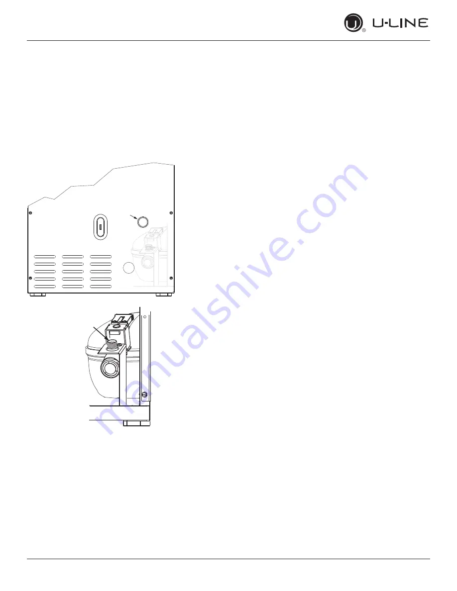
Water Hookup

1.  Turn off water supply and disconnect electrical supply 

to product prior to attempting installation.

2.  Remove the back panel.

3.  Thread water line through back panel hole (with 

bushing).

4.  Locate water valve inlet and connect to valve.

5.  Turn on water supply and check for leaks.

6.  Reinstall back panel.

4

11

Summary of Contents for Outdoor Onb115

Page 1: ...QUICK START GUIDE Outdoor Collection 30634 Rev_A 30634 Rev_E...

Page 2: ...consin USA and select products are available worldwide PRODUCT INFORMATION Looking for additional information on your product User Guides Spec Sheets CAD Drawings Compliance Documentation and Product...

Page 3: ...rge when you register your product on u line com See complete warranty for details CONTENTS Safety and Warning 4 Environmental Requirements 5 Electrical 5 Water Hookup 6 Drain 12 Door Swing 13 Door Ad...

Page 4: ...safety statement may result in minor or moderate personal injury property or equipment damage Your product may contain R600a Isobutane which is a flammable hydrocarbon To confirm check serial tag insi...

Page 5: ...repair or perform maintenance on the unit until the electricity has been disconnected Never remove the round grounding prong from the plug and never use a two prong grounding adapter Altering cutting...

Page 6: ...installation Use caution when handling back panel The edges could be sharp CAUTION CAUTION CAUTION USER GUIDE u line com Water Hookup Water Hookup PREPARE PLUMBING The water valve uses a standard 1 4...

Page 7: ...nlet 4 Break away filler feature in bushing with flat screwdriver 5 Thread water line through back panel hole with bushing 6 Locate water valve inlet and connect to valve 7 Turn on water supply and ch...

Page 8: ...installation Use caution when handling back panel The edges could be sharp CAUTION CAUTION CAUTION Water Hookup Clear Ice Machines USER GUIDE u line com Water Hookup Water Hookup PREPARE PLUMBING The...

Page 9: ...mal operation creates some vibration A water supply line contacting an internal component or cabinet wall can cause excessive noise during operation or damage to the line 4 On the back panel break awa...

Page 10: ...stallation Use caution when handling back panel The edges could be sharp CAUTION CAUTION CAUTION Water Hookup Nugget Ice Machines USER GUIDE u line com Water Hookup Water Hookup PREPARE PLUMBING The w...

Page 11: ...pply and disconnect electrical supply to product prior to attempting installation 2 Remove the back panel 3 Thread water line through back panel hole with bushing 4 Locate water valve inlet and connec...

Page 12: ...an NOT be located directly below the unit Unit has a solid base that will not allow the unit to drain below itself There is a possibility that hose connections may have loosened during shipment Verify...

Page 13: ...clearance is recommended from wall on hinge side to allow the door to open 90 Allow for additional space for any knobs or pulls installed on the integrated panel frame Stainless Steel models that are...

Page 14: ...t pinched on the hinge side of the door To align and adjust the door 1 Gently pry off hinge cover from top of unit 2 Loosen do not remove top and bottom hinge screws using a Torx T 25 screwdriver on t...

Page 15: ...bottom hinge Install two or three screws depending on model Replace nuts if used Prepare door for reinstallation 1 Remove gasket 2 Rotate gasket 180o and press firmly into the gasket channel starting...

Page 16: ...Loosen do not remove top and bottom hinge screws using a Torx T 25 screwdriver on the top and a 1 4 socket on the bottom 3 Align door squarely with cabinet 4 Make sure gasket is firmly in contact with...

Page 17: ...remove the two screws holding the assembly to the door Reinstall on the opposite end of the door 3 Rotate gasket 180o aligning notch with magnet assembly and pressing firmly into the gasket channel st...

Page 18: ...or gasket is not pinched on the hinge side of the door To align and adjust the door 1 Gently pry off hinge cover from top of unit 2 Loosen do not remove top and bottom hinge screws using a Torx T 25 s...

Page 19: ...nding on model Replace nuts if used Prepare door for reinstallation 1 Remove gasket This will reveal mounting holes for the magnet assembly 2 Remove magnet assembly from door with T 10 TORX driver Be...

Page 20: ...mm less than the opening s rear height Shorten the unit height in the front by adjusting the front legs This allows the unit to be gently tipped into the opening Readjust the front legs to level the u...

Page 21: ...splay and interior light return to normal operation This unit is Star K certified See www star k org for more details 18 21 CONTROL FUNCTION GUIDE FUNCTION COMMAND NOTES ON OFF Press and release Unit...

Page 22: ...s Star K certified See www star k org for more details 19 22 CONTROL FUNCTION GUIDE FUNCTION COMMAND NOTES ON OFF Press and release Unit will immediately turn On or OFF Adjust ice thickness See Ice se...

Page 23: ...set point for Refrigerator Freezer Enable Sabbath Mode Press and hold for 5 seconds and release The oF oC symbol will flash briefly after 5 seconds Interior light and display will go dark and remain s...

Page 24: ...Sabbath Mode Press and release Display and interior light return to normal operation Clean Mode See Cleaning section Showroom Mode Hold and for 5 seconds The F C symbol will flash Display will be lit...

Page 25: ...ed the unit is progressing towards the selected temperature Time to reach set point varies based upon ambient temperature temperature of product loaded door openings etc U Line recommends allowing the...

Page 26: ...rate cubes Shake the ice bucket instead During periods of limited use or high ambient temperatures it is common for cubes to fuse together Gently shake the bucket to break apart cubes If not using the...

Page 27: ...echecking ice thickness Ice is produced in layers resulting in a clear cube Ice in bin may develop surface frost which disappears when cube is placed in liquid Ice cubes in any given batch will vary s...

Page 28: ...ly melts in the bin the level of ice drops and ice production resumes This ensures a constant supply of fresh ice is always available THINNER BRIDGE THICKER BRIDGE DEEPER DIMPLE SHALLOWER DIMPLE 1 4 T...

Page 29: ...leanser and a nonabrasive cloth Always clean with the grain Always finish with Claire Stainless Steel Polish and Cleaner or comparable product to prevent further problems Using abrasive pads such as S...

Page 30: ...to force ice from the evaporator Damage may result 1 Turn the ice machine off and allow any ice to melt off of the evaporator 2 Remove all ice from the storage bin 3 Remove evaporator cover 4 Remove...

Page 31: ...150 250 4 months 250 400 3 months or sooner Hardness Level mg L ppm Cleaning Interval 0 66 6 months 67 133 4 months 134 200 3 months or sooner USER GUIDE Under normal conditions cleaning should be don...

Page 32: ...and some water will exit the vent tube Remove cleaning tube Optional for deeper cleaning allow solution to soak for 60 minutes b Press and release 5 04 will appear in the display a The machine will c...

Page 33: ...ng the hose and funnel slowly pour 1 5 quarts 48 oz of clean potable water into the ice dispenser tube Air and some water will exit the vent tube d Install new water filter Press and rotate 1 4 turn c...

Page 34: ...d or other natural disasters The product must be installed operated and maintained in accordance with your product s User Guide The remedies described above for each warranty are the only ones that U...

Reviews: