background image

2175BEVS/2175BEVOL Beverage Center

www.U-LineService.com

10

01/2007

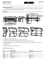
3. Create a relief for pivot plate by cutting notch in top 

corner and coinciding back corner of overlay frame. 
Refer to 

Figure 15

 for exact specifications.

Route notch in top corner of overlay frame as shown (see 
Top and Side Views). Top of notch is entire depth of 
frame, front to back. 

Width: 13/16"

Depth: 1/8"

Route notch in backside of top corner of overlay frame 
(see Back and Side Views). 

Width: 13/16"

Depth: 1/8"

Height: 1-17/32" from top edge of frame (less 1/8" for 
depth of notch on top of frame)

Radius of corner notch: 1/8" (see Back View)

4. Drill holes for pivot plate mounts (see 

Figure 15

, Back 

View).

5/16" diameter x 1/2" deep, from the routed surface 

CAUTION

Be careful not to drill too deep! Drilling holes too deep 
may destroy your door frame.

5. Drill hole for upper door hinge (top of frame) (see 

Figure 15

, Top View).

0.177" diameter

(#16 drill) x 11/16" deep

6. Drill hole for lower door hinge (see 

Figure 15

, Bottom 

View).

5/16" diameter x 1/4" deep

CAUTION

It is important to ensure that all drilled holes are drilled to 
the correct depth in order to avoid splits in the wood 
when hardware is installed.

Installation Instructions

Preparing Door

Note: 

Door is not attached. It 

is in a separate box inside the 
unit box and taped to the 
unit.

1. Lay door on a clean, flat 

surface with the gasket 
facing up. 

2. Pull gasket completely out 

of the groove. Start in the 
middle and pull outward, 
moving toward the edge
(see 

Figure 16

). This may take some force.

Note: 

Lay gasket flat on a clean surface to avoid 

disturbing interior magnet.

Checking Overlay Fit

1. Turn door over and lay overlay frame on front side of 

door. Make sure frame is fully seated on all four sides. 
See 

Figure 17

.

2. Visually check for gap between frame and glass. If there 

is an objectionable gap, follow steps under 

Applying 

Foam Tape to Overlay Frame

. If there is little or no gap, 

continue to 

Attaching the Overlay Frame

.

Top View

Back View

Bottom View

Side View

13/16"

1-17/32"

13/16"

13/32"

3/8"

Door Bottom:

5/16" Dia. x 1/4" Deep

Chamfer 1/32" x 45

°

3/8"

1/8"

1/8"

13/16"

7/16"

1/8"

13/32"

3/4"

13/32"

0.177" Dia. (#16 Drill)

x 11/16" Deep

5/16" Dia.

x 1/2" Deep

1/32" R

1/8" R

Figure 15

Door

Gasket

Figure 16

Not Fully Seated

Little or No Gap

Objectional Gap

Figure 17

Summary of Contents for 2175BEVOL

Page 1: ...4 354 0300 FAX 414 354 7905 Service Parts Tech Lines Phone 800 779 2547 FAX 414 354 5696 OnlineService U Line com 2007 U Line Corporation 01 2007 2175BEVS Beverage Center and 2175BEVOL Beverage Center with Overlay Installation Guide ...

Page 2: ... READ all instructions completely before attempting to install or operate the unit This unit requires connection to a grounded three prong polarized receptacle that has been placed by a qualified electrician in accordance with applicable electrical codes Safety Alert Definitions Safety items throughout this guide are labeled with a Danger Warning or Caution based on the risk type DANGER Danger mea...

Page 3: ...tion Card or register online at www U LineService com Once your unit is installed keep the Use and Care Guide and this Installation Guide in a safe place for future reference 2175BEVS units are Stainless Steel Stainless Steel units are covered with a protective coating and have been ordered left or right hand hinged The Stainless doors are not reversible 2175BEVOL units are Black with an unattache...

Page 4: ...at could lead to rust Some installations may require cleaning on a weekly basis Do not clean with steel wool pads Do not use cleaners that are not specifically intended for stainless steel this includes glass tile and counter cleaners If any surface discolors or rusting appears clean it quickly with Bon Ami or Barkeepers Friend Cleanser and a non abrasive cloth Always clean in the direction of the...

Page 5: ... units are designed to operate between 50 F 10 C and 110 F 40 C High ambient temperatures 110 F 40 C or higher may reduce the unit s ability to reach low temperatures For best performance keep the unit out of direct sunlight and away from heat generating equipment In climates where high humidity and dew points are present condensation may appear on outside surfaces This is considered normal The co...

Page 6: ...ied so that the wood trim could be stained to match décor or overlay frame The trim on the racks may be coated with a final finish or stained 2175BEVOL Models are designed for and require installation of an Overlay Frame If none of these treatments are to be included in this installation go on to 5 Adjust Door CAUTION To prevent permanent damage to the inner liner of the Beverage Center the wine r...

Page 7: ...se the inner liner of the unit to have a permanent odor which is not covered by the warranty If staining the trim is desired it must be done before the application of any type of final finish Review the following staining final finish and final finish only guidelines when staining and or sealing the wood to ensure proper adhesion and durability of the finish Note Glass in door is tinted Stain may ...

Page 8: ...y moving the hinge hardware to the opposite side The top hinge hardware will be used on the bottom of the other side and the bottom hinge hardware will be used on the top of the other side see Figure 7 Note ALL 2175BEVOL units are built and shipped as Right Handed units This section is only to be used if a Left Handed unit is desired To reverse the door 1 Remove screws 3 each top and bottom from n...

Page 9: ...n old hinge holes 3 each top and bottom Overlay Frame 2175BEVOL Units Only Frame Preparation An overlay frame covers the door frame to give a built in appearance Appropriate hardware and a copy of these instructions will be included in the unit IMPORTANT The thickness of the wood overlay frame must be 3 4 The door frame must not weigh more than 20 lbs 1 Create an overlay frame to the dimensions sh...

Page 10: ...to ensure that all drilled holes are drilled to the correct depth in order to avoid splits in the wood when hardware is installed Installation Instructions Preparing Door Note Door is not attached It is in a separate box inside the unit box and taped to the unit 1 Lay door on a clean flat surface with the gasket facing up 2 Pull gasket completely out of the groove Start in the middle and pull outw...

Page 11: ...o so can cause damage to overlay frame and or door Overlay frame will not sit flush to door if mounting hardware is not counter bored 3 Secure the front of the door to the back of the overlay frame using tape on all four corners as shown in Figure 20 Make sure all four edges are aligned 4 Place door and overlay frame on a flat clean protective surface Use the door frame holes as a guide to lightly...

Page 12: ...5 Adjust Door Checking Door Alignment The unit s door is aligned at the factory before shipment However its alignment could have been disturbed during shipment or during overlay frame installation IMPORTANT Properly aligned the door should be 1 8 below the top of the unit s cabinet NOT flush with the top see Figure 23 1 Compare the top edge of the door to the top edge of the cabinet 2 If the door ...

Page 13: ...lectrical installation must observe all state and local codes This unit requires connection to a grounded three prong polarized receptacle that has been placed by a qualified electrician The unit requires a grounded and polarized 115 VAC 60 Hz 15A power supply normal household current An individual properly grounded branch circuit or circuit breaker is recommended GFCI ground fault circuit interru...

Page 14: ...ing adjust the rear feet to achieve a total unit rear height of 1 8 less than the opening s rear height Shorten the unit height in the front by adjusting the front feet This allows the unit to be gently tipped into the opening Readjust the front feet to level the unit after it is correctly positioned in the opening Installation Troubleshooting Problem Q The door remains open unless it is pushed cl...

Page 15: ... not tripped Check to see that control is turned on Problem Q Light is on with door closed Solution A Touch the LIGHT icon on the display panel This will cancel out the light function and just allow the light to turn on and off with the door opening and closing The Beverage Center has an interior light that is illuminated when the door is opened The light can be left on while the door is closed by...

Page 16: ...d itself as the leader in built in undercounter ice making refrigeration and wine storage appliances Who to Call Service Information If the need for service arises call the U Line Customer Care Center directly 800 779 2547 To ensure accurate assistance please have your Model Number and Serial Number and an explanation of the problem The Model and Serial Number plate is located inside unit at upper...

Reviews: