56 Maintenance
Dimension BST 1200es / SST 1200 es User Guide
3. Remove the XY tip calibration part from the Dimension printer.
4. Inspect the part and calibrate the X and Y axes (See
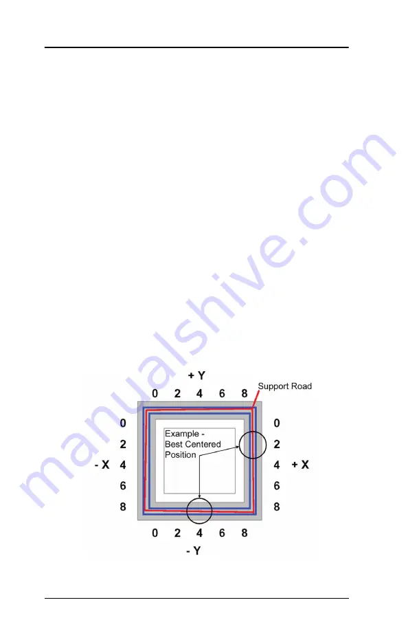
A. Use the magnifier from the Startup Kit to view the support
road (shown in red).
B. Identify the location on the +X
or
–X side of the part where
the support road is best centered within the model
boundaries (shown in blue).
C. Read the number closest to this location. This is the
required X Tip Offset adjustment, in mils. If the number is
on the -X side, a negative offset is required.
D. Select
Increment
or
Decrement
to input the X offset
adjustment - the value will change in the upper display
window (by default, the printer will be ready to accept the X
value).
E. When you are satisfied with your X offset value,
Select Y
and repeat the procedure to identify and input the required
Y Tip Offset adjustment.
5. Select
Done
after you have input the X and Y offsets. The
printer will return to
Maintenance
.
Figure 23: Example XY Tip Offset Part.
This example requires an adjustment of X = + 2 mils, Y = - 4 mils
Summary of Contents for BST 1200es
Page 1: ...BST 1200es SST 1200es User Guide...
Page 6: ...6 DimensionBST1200es SST1200esUserGuide...
Page 10: ...10 DimensionBST1200es SST1200esUserGuide...
Page 72: ...72 Troubleshooting DimensionBST1200es SST1200esUserGuide...
Page 73: ...Dimension BST 1200es SST 1200es User Guide Troubleshooting 73...


