


NORA-W10 series - System integration manual
UBX-22005601 - R04
Design-in
Page 21 of 56
C1-Public
•
Integrated antennas such as patch-like antennas:
o
Internal integrated antennas imply physical restriction to the PCB design:
Integrated antenna excites RF currents on its counterpoise, typically the PCB ground plane of
the device that becomes part of the antenna; its dimension defines the minimum frequency
that can be radiated. Therefore, the ground plane can be reduced to a minimum size that
should be similar to the quarter of the wavelength of the minimum frequency that has to be
radiated, given that the orientation of the ground plane related to the antenna element must
be considered.
The RF isolation between antennas in the system must be as high as possible and the
correlation between the 3D radiation patterns of the two antennas has to be as low as possible.
In general, an RF separation of at least a quarter wavelength between the two antennas is
required to achieve a maximum isolation and low pattern correlation; increased separation
should be considered, if possible, to maximize the performance and fulfil the requirements
described in
As a numerical example, the physical restriction to the PCB design can be considered to be:
Frequency = 2.4 GHz
→
Wavelength = 12.5 cm
→
Quarter wavelength = 3.125 cm
2
o
Radiation performance depends on the whole product and antenna system design, including
product mechanical design and usage. Antennas should be selected with optimal radiating
performance in the operating bands according to the mechanical specifications of the PCB and
the whole product.
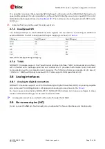
summarizes the requirements for the antenna RF interface:
Item
Requirements
Remarks
Impedance
50
nominal characteristic
impedance
The impedance of the antenna RF connection must match
the 50
impedance of the
ANT
pin.
Frequency Range
2400 - 2500 MHz
Wi-Fi and Bluetooth.
Return Loss
S
11
< -10 dB (VSWR < 2:1)
recommended
S
11
< -6 dB (VSWR < 3:1) acceptable
The Return loss or the S
11
, as the VSWR, refers to the
amount of reflected power, measuring how well the primary
antenna RF connection matches the 50
characteristic
impedance of the
ANT
pin.
The impedance of the antenna termination must match as
much as possible the 50
nominal impedance of the
ANT
pin over the operating frequency range, thus maximizing
the amount of the power transferred to the antenna.
Efficiency
> -1.5 dB ( > 70% ) recommended
> -3.0 dB ( > 50% ) acceptable
The radiation efficiency is the ratio of the radiated power to
the power delivered to the antenna input; the efficiency is a
measure of how well an antenna receives or transmits.
Maximum Gain
Refer to Data sheet
The maximum antenna gain must not exceed the value
specified in type approval documentation to comply with
the radiation exposure limits specified by regulatory
agencies.
Table 5: Summary of antenna interface (ANT) requirements for NORA-W101
2
Wavelength referred to a signal propagating over the air.