


NORA-W10 series - System integration manual
UBX-22005601 - R04
Module integration
Page 13 of 56
C1-Public
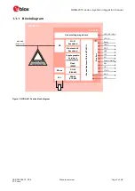
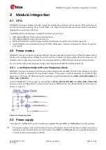
2.3.1
Module supply input (VCC)
NORA-W10 series modules use an integrated Linear Voltage converter to transform and stabilize the
supply voltage applied to the
VCC
pin. Typical Input voltage at
VCC
and
VCC_IO
pins is 3.3 V with an
operating voltage range between 3.3 V and 3.6 V.
⚠
NORA-W10 must be supplied with a Class-1 PS1 (reg. IEC 62368-1) power supply.
2.3.2
Digital I/O interfaces reference voltage (VCC_IO)
NORA-W10 modules currently support 3.0
–
3.6 V IO voltage level only.
2.3.3
VCC application circuits
The power for NORA-W10 series modules is applied through the
VCC
pins. These supplies are taken
from either of the following sources:
•
Switching Mode Power Supply (SMPS)
•
Low Drop Out (LDO) regulator
An SMPS is the ideal design choice when the available primary supply source is significantly higher
than the operating supply voltage of the module. This offers the best power efficiency for the
application design and minimizes the amount of current drawn from the main supply source.
⚠
When taking VCC supplies from an SMPS make sure that the AC ripple voltage is kept as low as
possible at the switching frequency. Design layouts should focus on minimizing the impact of any
high-frequency ringing.
Use an LDO linear regulator for primary VCC supplies that have a relatively low voltage. As LDO
regulators dissipate power linearly related to the step-down voltage, LDOs are not recommended for
step down of high voltages.
DC/DC efficiency should be regarded as a trade-off between the active and idle duty cycles of an
application. Although some DC/DC devices achieve high efficiency at light loads, these efficiencies
typically degrade as soon as the idle current drops below a few milliamps. This can have a negative
impact on the life of the battery.
If decoupling capacitors are needed on the supply rails, it is best practice to position these as close as
possible to the NORA-W10 series module. The power routing of some host system designs makes
decoupling capacitance unnecessary.
For electrical specifications, see also the appropriate NORA-W10 series data sheet
2.4
Module reset
NORA-W10 is reset (rebooted) by setting the
RESET_N
pin to low.
RESET_N
has an internal pull-up
resistor setting its default state to high. The low-
level input triggers a “hardware reset” of the module.
The
RESET_N
signal should be driven by an open drain, open collector, or contact switch. The chip
works at the minimum power when
RESET_N
is low (off).
2.5
Bootstrap pins
Several module pins related to the boot configuration must be strapped correctly using either pull-up
or pull-down resistors, as shown in
⚠
Boot strap pins should be avoided if other GPIO pins can be used instead. Note that all module pins
shown in bold are configured to their default state internally in the ESP32-S3 chip and must NOT
be configured externally.