


LILY-W1 series - System integration manual
UBX-15027600 - R09
Design-in
Page 21 of 64
C1 - Public
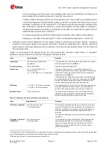
TDK
B8343
B39242B8343P810
Requires external matching network (two inductors)
TDK
B9604
B39242B9604P810
Requires external matching network (one inductor)
TriQuint
885071
885071
Requires external matching network (two inductors)
TriQuint
885032
885032
Avago
ACPF-7424
ACPF-7424
No external matching required
Taiyo Yuden
FBAR dev.
F6HF2G441AF46
Requires external matching network (two inductors)
Table 13: LTE filter, recommended part list.
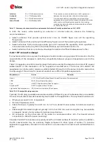
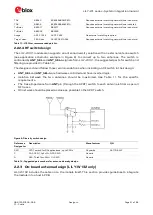
2.2.2.4
RF switch design
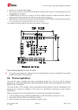
The LILY-W131 module also supports an antenna diversity solution with an external antenna switch
(see application schematic example in Figure 6) to connect up to two antennas. The switch is
controlled by
ANT_SEL
and
ANT_SEL-n
signals from LILY-W131; the suggested parts for switch and
filtering are provided in Table 14.
The designers should follow those recommendations when including an RF switch in their design:
•
ANT_SEL
and
ANT_SEL-n
are hardware controlled and have inverted logic.
•
Isolation between the two antennas should be maximized. See Table 11 for the specific
requirements.
•
The trace impedance from
ANT
pin (through the SPDT) switch to each antenna is 50
Ω
as per all
RF traces.
•
RC network should be placed as close as possible to the SPDT switch.
Figure 6: Diversity switch design
Reference
Designator
Description
Manufacturer
P/N
SW1
SPDT switch for RF applications, up to 3GHz
Skyworks
AS179-92LF
C
CAP, CER, 10pF
±
5%, NP0, SMD
Generic
R
RES, Thick film, 22
Ω ±5%
, SMD
Generic
Table 14: Suggested part numbers for antenna diversity design
2.2.3
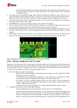
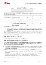
On-board antenna design (LILY-W132 only)
LILY-W132 includes the antenna on the module itself. This section provides guidelines to integrate
the module into a host’s PCB.