C030-R412M - User Guide
UBX-19010121 - R01
Hardware description
Page 13 of 27
2.4
Connectors
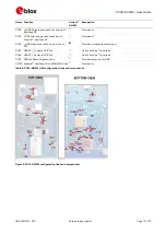
The C030-R412M has various connectors as listed in
. See
Name
Function
Description
Section
ETH1
Ethernet receptacle
10/100 Mb/s Ethernet network connector
Utility
J6
Auxiliary 5V USB
Micro USB device connector for auxiliary 5 VDC supply input to
connect a high current 5 VDC PSU
Utility
J1
Debug USB
Micro USB device connector for 5 VDC supply and ST-Link/CMSIS-
DAP debug interface
Utility
J2
Micro SD card socket
Micro SD card holder for FAT file system
Application
J3
Serial USB sniffer
Micro USB device connector for 5 VDC supply and serial USB sniffer
interface
Application
J4/J5
LiPo battery connector LiPo chargeable battery connector. J4: Not populated alternative
connector, J5: Molex 22-05-7035
Application
J7
Cellular module USB
Micro USB device connector for cellular module USB interface
Application
J8
SIM card holder
SIM card holder (for C030-N211 and C030-R410M only)
Application
SWD
InterfaceMCU debug
10-pin Arm Cortex debug connector for InterfaceMCU (may not be
populated)
Utility
ST_SWD
InterfaceMCU debug
Tag-Connect-NL Plug-of-Nails™ connector compatible PCB touch
points footprint for InterfaceMCU
Utility
SWD_TARGET HostMCU debug
10-pin Arm Cortex debug connector for InterfaceMCU (may not be
populated)
Application
SWD_TGT1
HostMCU debug
Tag-Connect-NL Plug-of-Nails connector compatible PCB touch
points footprint for HostMCU
Application
ANT
Cellular main antenna
SMA connector for the cellular module primary antenna (ANT1, Tx/Rx) Application
GPSANT
GNSS receiver antenna SMA connector for the ZOE-M8B GNSS receiver
Application
Table 3: C030-R412M connector description
☞
The J2 Micro SD card socket shares the Arduino interface D10 to D13 pins, which are used as an
SPI bus to the HostMCU SPI4 peripheral. The D10 pin (NSS) is used as an SD card SPI slave select
signal. When the SPI bus on the Arduino interface is utilized by other SPI slaves on daughter
boards, free Arduino digital IO lines should be utilized for slave select signals.
⚠
As the SD card interface and its supply voltage are designed to work with 3.3 VDC, the SD card
socket shall not be used when the Arduino interface IOREF voltage level is set to higher than
3.3 VDC. Such usage could cause a permanent damage and/or a failure to an SD card inserted in
the J2 socket and the C030-R412M’s Arduino™ interface level translators. (See R152 and R153
links in


