background image

Operating Instructions

Product description

PPH25RR*** / 000

1-5

1.8

Hydraulics

1.8.1

Main circuit

Main circuit 

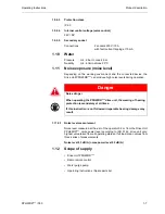
3 pumps

Flow rates can be set to 45 / 50 / 60 / 70 l/min., depending on the cutting
tool speed required

Flow rates and pressures

Stage I

45 l/min

230 bar

Stage II

50 l/min

200 bar

Stage III

60 l/min

170 bar

Stage IV

70 l/min

140 bar

Same power in all stages

1.8.2

Feed circuits

Feed circuits: 

1 pump

Two hydraulic feed outputs which can be regulated independently of each
other, controlled using radio remote control.

1.8.3

Oil tank

Oil tank volume:

10 litres

Filter quality:

20 µm

1.8.4

Return oil filter

Type:

Tank-mounted filter

1.8.5

Oil cooling

Oil cooler:

Water/oil heat exchanger

1.8.6

Couplings and hoses

Plug-in couplings

Type FD and FF, non-drip

Hoses

Length 8m (filled with hydraulic oil)

1.8.7

Oil quality

TYROLIT Hydrostress AG recommends:

Hydraulic oil:

HLP/ISO VG 46

Summary of Contents for PPH25RR Series

Page 1: ...Operating Instructions Spare Parts List 10983823 en 17 7 07 Drive Unit PPH25RR Index 000...

Page 2: ...al changes without prior notice Copyright 2007 TYROLIT Hydrostress AG CH 8330 Pf ffikon ZH All rights reserved in particular the copying and translation rights The reprinting of these Operating Instru...

Page 3: ...quipment 6 1 10 Water 7 1 11 Noise exposure noise level 7 1 12 Scope of supply 7 1 13 Country list for radio transmission frequency 8 2 Safety instructions 1 2 1 General 1 2 2 General safety rules 1 2...

Page 4: ...orrective maintenance 1 7 1 Troubleshooting 1 7 2 Storage 4 8 Transport 1 8 1 Transport 1 8 2 Safety instructions 1 8 3 Crane shackles and transport handles 2 9 Disposal 1 9 1 General 1 9 2 Disposal r...

Page 5: ...n guarantee quality and interchangeability In the case of neglected or inappropriate maintenance we will be unable to accept the warranty commitment as specified in our terms of delivery Any repair wo...

Page 6: ...the following system Drive Unit PPH25RR 0 3 Standards These Operating Instructions have been prepared in accordance with the CE Machinery Directive Appendix I and with the relevant standards in force...

Page 7: ...insaws The applicable mandatory limitations on use and other parameters are con tained in Chapter 1 Technical data 1 7 1 4 1 2 Safety measures Any use other than for the intended purpose see Chapter 1...

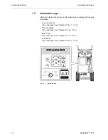
Page 8: ...n information sign containing the following information Hose connections For a description see Chapter 5 5 3 2 1 5 2 Pressure stages For a description see Chapter 5 5 4 3 5 8 Risk of frost For a descr...

Page 9: ...2 Standards applied Description Hydraulic drive unit Type designation Drive Unit PPH25RR Year of construction 2007 EN12100 1 EN 12100 2 Safety of machinery Basic concepts general design principles EN...

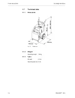
Page 10: ...ption Operating Instructions 1 4 PPH25RR 000 1 7 Technical data 1 7 1 Dimensions Fig 1 3 Dimensions 1 7 2 Weight Operating weight 160 kg 1 7 3 Tyres Wheel 30 cm Operating pressure 3 bar 65 cm 105 120...

Page 11: ...me power in all stages 1 8 2 Feed circuits Feed circuits 1 pump Two hydraulic feed outputs which can be regulated independently of each other controlled using radio remote control 1 8 3 Oil tank Oil t...

Page 12: ...z 3480 rpm 1 9 2 1 Motor protection Thermal protection Winding thermostat Electrical protection Thermal relay 1 9 2 2 Cooling Water cooling Cooling channels in the aluminium Throughput of cooling wate...

Page 13: ...evels during operation 1 11 0 1 Noise level measurement Noise level measured at the ear of the operator 0 5 m from the Drive Unit PPH25RR noise power level according to ISO 3744 drive unit only highes...

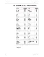
Page 14: ...d 434 China 419 Portugal 434 Denmark 434 Puerto Rico 458 Germany 434 Romania 434 Finland 434 Russia 434 France 434 Sweden 434 Greece 434 Switzerland 434 Great Britain 434 Singapore 434 Hong Kong 458 S...

Page 15: ...ive or neglected maintenance work Independently performed conversions and alterations may affect safety and are not permitted 2 2 General safety rules 2 2 1 Statutory provisions The generally applicab...

Page 16: ...as been switched off disconnected from the mains and is at standstill Safety components in particular may only be removed and refitted by authorised personnel see Chapter 2 2 4 1 2 3 Before switching...

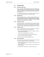
Page 17: ...ed by TYROLIT Hydrostress AG is the primary legal en tity responsible for the correct use of the product and for the training and assignment of the authorised personnel The operator sets out the manda...

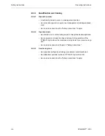
Page 18: ...ter 2 4 6 2 Operator user Has trained as a concrete cutting expert or has professional experience Has received an introduction basic training to the operation of the TYROLIT Hydrostress AG machines an...

Page 19: ...rotechnically trained personnel Failure to comply with this regulation may lead to serious physical injury or death Secondary damage such as fires may also occur Warning Danger of allergic reactions i...

Page 20: ...Safety instructions Operating Instructions 2 6 PPH25RR 000...

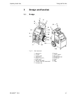
Page 21: ...unit 10 Antenna 2 Oil cooler 11 Oil level indicator 3 Pressure gauge 12 Radio receiver 4 Water valve 13 Electrical connection 5 Suspension shackle 14 Electrical box 6 Electric motor 15 Wheel 7 Radio r...

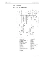
Page 22: ...e relief valve 22 Nipple 6 Pressure gauge 0 400 bar 23 Coupling 7 Oil and water cooler 24 Water valve 8 Aeration filter 25 Pressure valve 20 bar 9 Oil level 26 Proportional valve 5 120 bar 10 Return f...

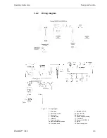
Page 23: ...Wiring diagram 1 Elec box 8 EMERG STOP 2 Reversing switch 9a Hour counter 3 Contactor 9b Rotation lock 4 Thermal relay 10 Phase sequence relay 5 Interlock 11 Time relay 6 Circuit breaker 12 Connector...

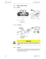
Page 24: ...ry 2 Battery charger 3 Cable insert 4 Battery insert 3 3 2 Function The radio remote control allows a secure simple and mobile method of working The operator can at all times be in a position where he...

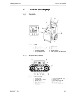
Page 25: ...erse switch 9 Remote controller 5 Device protective switch 10 Cable connection of remote controller 4 1 1 Radio remote control Fig 4 2 Radio remote control 1 Locking switch 7 Pressure stage selector s...

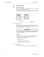
Page 26: ...l safety device The operating principle of the safety socket is the same as that of a residual current circuit breaker Monitoring The safety socket must be checked monthly during operation The check c...

Page 27: ...ce switch interrupts the circuit in the event of a current surge more than 13A The circuit is restored by pressing the device switch 4 2 4 Cable connection of remote controller The radio remote contro...

Page 28: ...ator 3 Pressure gauge of feed motors 4 3 1 Hour counter The hour counter allows for precise observance of the service intervals Fig 4 6 Hour counter 4 3 2 Pilot lamp radio battery Fig 4 7 LED pilot la...

Page 29: ...to 400 bar 2 Pressure gauge of feed motors 0 bar to 250 bar 4 3 4 Oil level indicator Fig 4 9 Oil level indicator Information The quantity of oil between oil MIN and oil MAX is 1 5 litres Different t...

Page 30: ...Controls and displays Operating Instructions 4 6 PPH25RR 000...

Page 31: ...l hydraulic units that are designed for the pressure and delivery volume of the Drive Unit PPH25RR see Chapter 1 1 8 1 5 Warning A danger will arise if the Drive Unit PPH25RR is operated with a differ...

Page 32: ...the water line properly connected to the Drive Unit PPH25RR Is there sufficient oil in the Drive Unit PPH25RR Is there any damage to cables or plugs Has the EMERGENCY STOP been reset 5 3 2 Connecting...

Page 33: ...ear it click Twist the locking ring of the coupling 5 3 2 3 Release pressure in the Drive Unit PPH25RR Proceed as follows Turn the forward reverse switch on the Drive Unit PPH25RR to posi tion 1 2 Swi...

Page 34: ...The cable insert included in the scope of supply allows connection of the remote controller to the Drive Unit PPH25RR The cable length is 10 m Cable operation makes it possible to work in areas where...

Page 35: ...G STOP on the radio remote control Deactivating EMERGENCY STOP Fig 5 4 Deactivating EMERGENCY STOP Proceed as follows The following controls must be moved into the 0 position Feed joystick 3 Main moto...

Page 36: ...i tion 1 Switch on the radio remote control by means of the Start switch Pilot lamp lights up red first of all A signal tone sounds simultaneously Pilot lamp lights up green Second signal tone sounds...

Page 37: ...art The soft start is used mainly for diamond wire sawing Proceed as follows Start the Drive Unit PPH25RR see Chapter 5 5 4 1 5 6 Turn the main motor potentiometer to the 0 position Select the desired...

Page 38: ...he main motor potentiometer from 0 to 100 5 4 4 Power control The power of the main motor and the feed motor is controlled via the po tentiometer Fig 5 7 Potentiometers 1 Feed motor potentiometer 2 Ma...

Page 39: ...feed 5 4 6 Feed locking So that the joystick does not have to be held in position during the travel feed motion the travel feed can be locked Proceed as follows Push the joystick in the desired trave...

Page 40: ...Unit PPH25RR to the 0 position 5 5 After the work Proceed as follows Unplug the mains plug Drive Unit PPH25RR Uncouple the water supply on the Drive Unit PPH25RR Open the water valve on the Drive Uni...

Page 41: ...tion leakproof condition cleanliness X X X X Check oil level see Chapter 4 4 3 4 4 5 X X X Replace hydraulic oil see Chapter 6 6 1 2 6 2 X Water economy Water line leakproof condition cleanliness X X...

Page 42: ...ns Information In order to prevent damage from frost cracks if there is a risk of frost or prior to extended breaks in work the cooling water must be blown out of the system Use the TYROLIT purge pump...

Page 43: ...across flats 18 mm for the oil drain plug Approx 10 litres of hydraulic oil Fig 6 1 Replacing hydraulic oil 1 Oil drain plug Proceed as follows Place the collecting pan below the oil drain plug 1 Open...

Page 44: ...elect the pressure stage 4 see Chapter 5 5 4 3 5 8 Allow the Drive Unit PPH25RR to run for a maximum of 5 seconds Switch off the Drive Unit PPH25RR see Chapter 5 5 4 7 5 10 Wait for 1 minute Repeat th...

Page 45: ...ases incorrectly connected Check power supply Phase missing Check power supply Remote controller not switched on or controls in wrong position see Chapter 5 5 4 1 5 6 No radio connection Test with cab...

Page 46: ...r 1 1 9 1 1 6 Check power supply see Chapter 1 1 9 1 1 6 Use mains cable with correct cross section see Chapter 5 5 3 1 5 2 Check water circuit see Chapter 1 1 10 1 7 Defective plug connection Check p...

Page 47: ...fault as accurately as possible Note the type and index designation of your unit name plate Have the Operating Instructions close to hand Fig 7 1 Name plate No water emerging Water line is blocked Cl...

Page 48: ...RR 000 7 2 Storage The Drive Unit PPH25RR consists partially of material which can cor rode If you take the unit out of service for an extended period proceed as follows Blow out the water from the wa...

Page 49: ...taking the Drive Unit PPH25RR out of service Danger Danger from incorrect crane transport Crane transport should only be carried out using the crane shack les provided Only undertake crane transport...

Page 50: ...dles 1 Crane shackles 2 Transport handles with hose bracket Danger Danger of falling parts When crane transport is used the Drive Unit PPH25RR must be transported alone without the radio remote contro...

Page 51: ...to observe the following safety instructions especially in re lation to disposal of the Drive Unit PPH25RR 9 1 2 Personnel qualifications Personnel who carry out the work described in this chapter mus...

Page 52: ...onents of the Drive Unit PPH25RR must be dismantled This is performed by the client s personnel The dismantled parts of the device are sorted by material type and sent separately to the appropriate co...

Reviews: