4
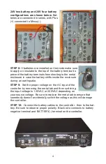
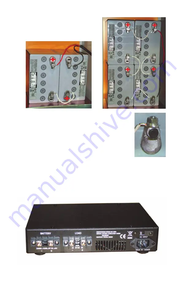
24V two battery and 24V four battery
configurations are shown below.
Bat-
teries are connected in series, with Plus
(+) connected to Minus(-).
STEP 8:
If batteries are installed on their side make sure
to apply an insulator to the top of the battery terminal to
prevent the battery terminals from shorting to the metal
enclosure in case the battery shifts inside the enclosure
during an earthquake.
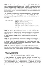
STEP 9:
Set the proper voltage on the AC input of the
controller by removing the metal tab and then switching
the input voltage to 120VAC or 240VAC depending on
your source voltage. Be sure to replace the metal tab to ensure that
somebody doesn’t accidentally switch the voltage as this will damage
the controller.
STEP 10:
Connect the battery cables to the controller , then to the bat-
tery. Be sure to observe proper polarity. Black wire connects to battery
negative terminal and BATTERY(-) terminal on the controller.


