INSTALLATION
NOTES
Residential Fire Sprinkler Sys-
tems should only be designed and
installed by those competent and
completely familiar with auto-
matic sprinkler system design, in-
stallation procedures, and tech-
niques.
The Technical Data Department
should be contacted relative to
any questions.
Do not install any bulb type sprin-
kler if the bulb is cracked or if
there is a loss of liquid from the
bulb. With the sprinkler held
horizontal, a small air bubble
with an approximate diameter of
1/16 inch should be be present.
The Model F685 Designer Residential
Sprinklers must be installed in accord-
ance with the following instructions:
1. The F685 Sprinkler must be installed
with the centerline of the waterway
horizontal and perpendicular to the
backwall surface.
NOTE
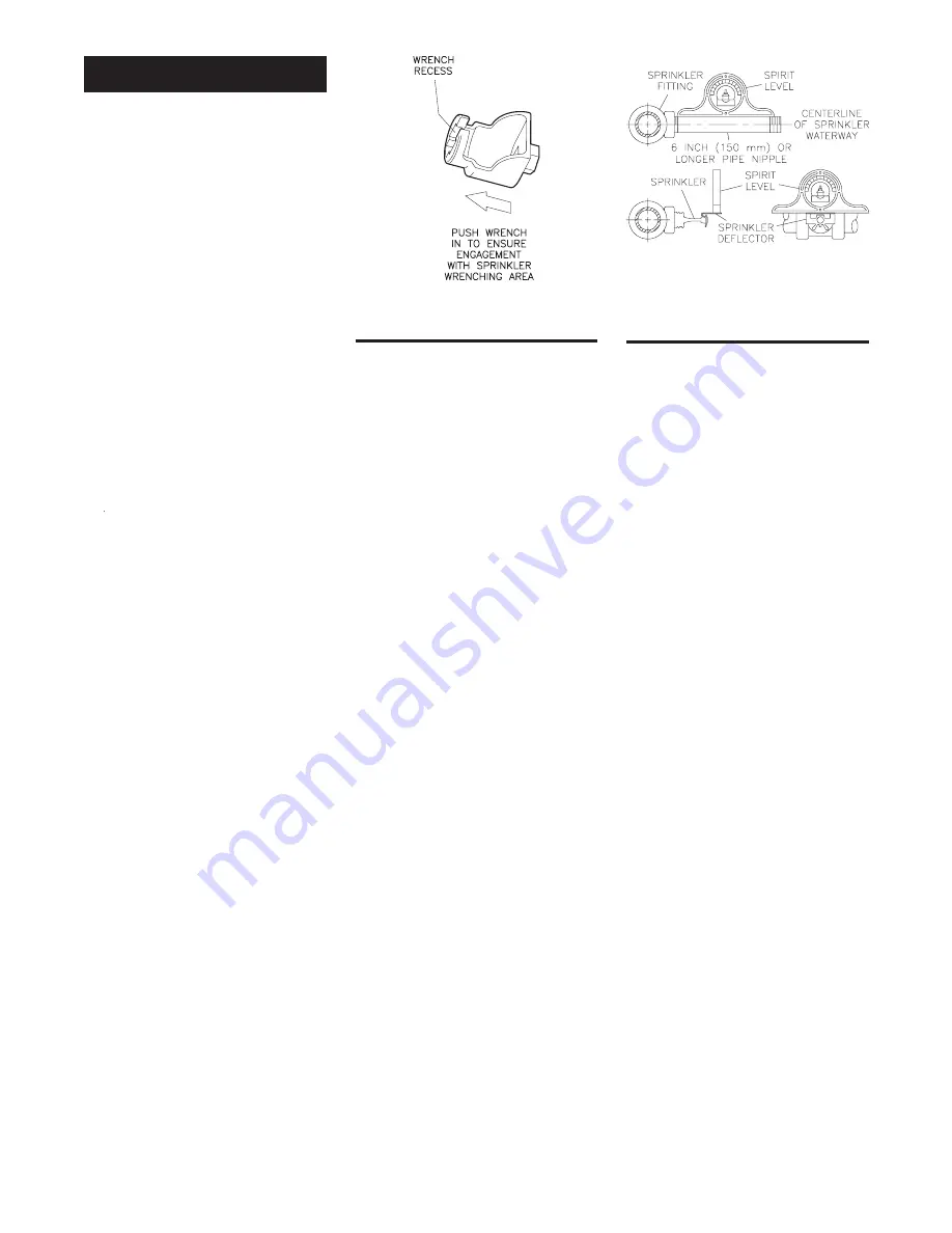
It is recommended that a spirit
level be used to level the sprin-
kler fitting as shown in Figure
E and that a square be used to
check perpendicularity of the
waterway centerline to the
mounting surface.
2. Prior to installing each Sprinkler,
verify that the outer face of the mat-
ing fitting is within the proper range
of distance of the mounting surface,
which can be accommodated by the
particular type of escutcheon plate
being used.
When installing a Model F685 Pen-
dent Sprinkler with the F705 Re-
cessed Escutcheon, for best overall
appearance, use Dimension “A” in-
dicated under the “Fully Recessed
Dimensions” heading of Figure B-2.
Otherwise, use Dimension “A” under
the “High Adjustment Dimensions”
heading. In either case, the remain-
ing adjustment can be used to com-
pensate for the possible manufac-
turing variations in the take-out of
the fitting, as well as in the make-in
of the sprinklers (as permitted by
ANSI B1.20.1).
3. After installing the F705 Mounting
Plate (or other escutcheon, as appli-
cable) over the sprinkler threads and
with pipe thread sealant applied to
the pipe threads, hand tighten the
sprinkler into the sprinkler fitting.
4. Wrench tighten the sprinkler using
only the W-Type 7 Sprinkler Wrench
(Ref. Figure D). The wrench recess
of the W-Type 7 is to be applied to
the sprinkler wrench flats (Ref. Fig-
ure A). The word “TOP” on the De-
flector must face upwards towards
the ceiling.
NOTES
A leak tight 1/2 inch NPT sprin-
kler joint should be obtained
with a torque of 7 to 14 ft.lbs. (9,5
to 19,0 Nm). A maximum of 21
ft.lbs. (28,5 Nm) of torque is to be
used to install sprinklers.
Higher levels of torque may dis-
tort the sprinkler orifice seat
with consequent leakage.
It is recommended that a spirit
level be used to level the Deflec-
tor, as shown in Figure E. The
Deflector slopes slightly up-
ward from back to front; conse-
quently, the level needs to be po-
sitioned along the front edge of
the Deflector.
Do not attempt to make-up for
insufficient adjustment in an
Escutcheon Plate by under- or
over-tightening the Sprinkler.
Readjust the position of the
sprinkler fitting to suit.
5. In recessed horizontal sprinkler in-
stallations, after the wall has been
installed or the finish coat has been
applied, slide on the F705 Closure
over the Model F685 Sprinkler and
push the Closure over the Mounting
Plate until its flange comes in con-
tact with the wall.
—6—
FIGURE D
W-TYPE 7 SPRINKLER WRENCH
FIGURE E
LEVELING OF
SPRINKLER FITTING
AND DEFLECTOR
OBSOLETE


