


3.2 Disassembly Flowchart
The
following flowchart outlines the disassembly procedure.
Rear Components
Chassis rear cover
Air Duct
Mainboard
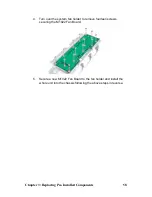
Power Supply
DIMMs
CPU/Heatsink Assembly
PCI Card
Mainboard
Front Components
Chassis rear cover
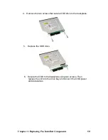
ODD
PCBs
FAN
M1003 LED
Control Board
M1223 HDD
Backplane
M1022 FAN
Board
M1025
PDB
Chapter 3: Replacing Pre-Installed Components
44
Summary of Contents for Transport TN27 B4987
Page 1: ...Transport TN27 B4987 Service Engineer s Manual ...
Page 2: ......
Page 17: ...8 Rail Kit Rail with Bracket x 2 Screw Sack Chapter 1 Overview 8 ...
Page 31: ...22 1 6 6 System Block Diagram Chapter 1 Overview 22 ...
Page 62: ...3 6 1 M1003 LED Control Board Features 53 Chapter 3 Replacing Pre Installed Components ...
Page 128: ...Registration Info Install Path SDP WSD Activation 119 ...
Page 129: ...Complete Custom Components Selection Only SDP or WSD may be installed Not both Below SDK 120 ...


