46
Chapter 3: Replacing Pre-Installed Components
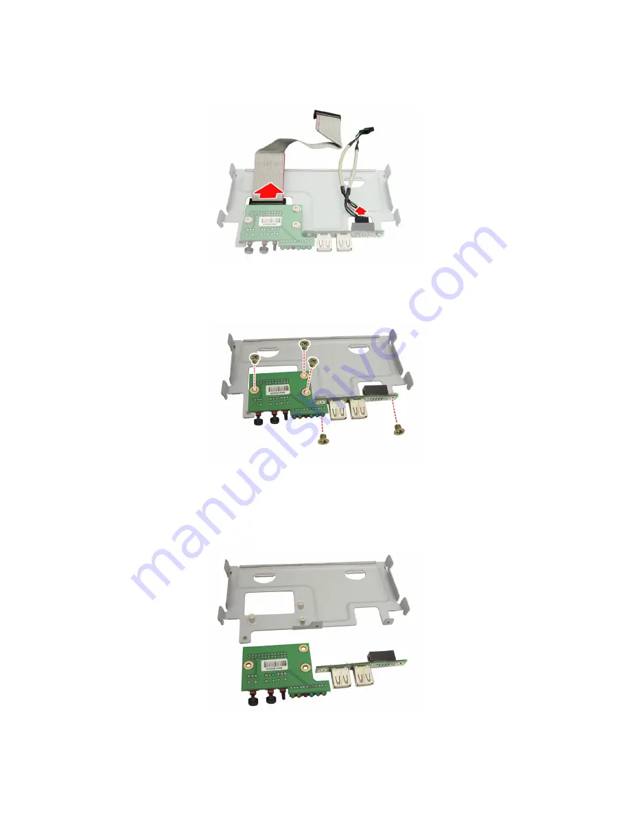
4. Remove the LED control board and USB cables from the
LED control board and USB adapter board.
5. Remove the five screws securing the LED control board
and USB adapter board to the bracket.
6. Release the LED control board and USB adapter board
from bracket. After replacement, insert and secure the
unit to the chassis following the above procedure in
reverse.
Summary of Contents for Tank TA26 B5397
Page 1: ...Tank TA26 B5397 Service Engineer s Manual...
Page 2: ......
Page 14: ...6 Chapter 1 Overview Screw Pack Sliding Rail FDD Rails FDD Power Cable TYAN Logo...
Page 17: ...Chapter 1 Overview 9 1 5 4 Motherboard Layout...
Page 19: ...Chapter 1 Overview 11 1 5 6 System Block Diagram...
Page 24: ...16 Chapter 2 Setting Up 3 Unscrew the fan duct...
Page 30: ...22 Chapter 2 Setting Up The following chart outlines the suggested rules for populating memory...
Page 42: ...34 Chapter 2 Setting Up NOTE...
Page 47: ...Chapter 3 Replacing Pre Installed Components 39 3 Unscrew the fan duct...
Page 72: ...64 Chapter 3 Replacing Pre Installed Components NOTE...


