S2056 Tomcat i810e
23
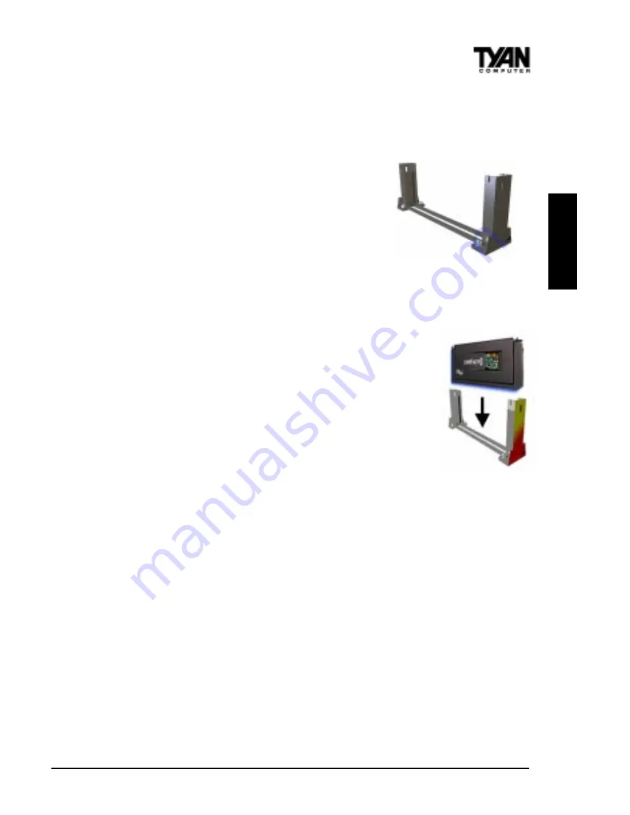
Figure 2-9
Figure 2-10
carefully line up the key notch on the retention module with the key pin on the
CPU slot (the key pin on the CPU slot indicates the correct orientation of the
CPU) See Figure 2-8 on the previous page.
Drop the retention module (Figure 2-9 right) down
over the CPU slot so that the retention module sits
flat against the motherboard. Tighten the screws in a
clockwise manner to secure the module to the board.
Warning: Do not overtighten the screws as you may
damage the module and/or the motherboard.
Installing the CPU with Active Cooling
When the retention module is securely installed, you are ready
to plug in the CPU. Lower the CPU into the slot and press
down firmly on the CPU until you hear a click (see Figure 2-
10 right). This clicking sound indicates that the CPU is fully
locked into the retention module. If you have an active cooler,
you will also need to connect the CPUs cooling fan cable to
the cooling fan power connector on the board. Locate the
cooling fan connector (e.g. FAN1) on the motherboard. Plug
the CPUs cooling fan cable into the cooling fan connector on
the board. There will be a plastic clip assembly similar to that
of the ATX power connector that will force you to connect the
fan cable correctly (see Figure 2-11 on the following page).
Removing the CPU.
To remove the CPU, move the locks to the center of the CPU. A click will be
heard when the CPU has been unlocked. Gently pull up on the CPU, taking
care not to bend the motherboard or the CPU retention module.
To remove the lock from the retention module, gently press the ends of the
locks inward and pull.
INST
A
LL


