background image


http://www.tyan.com


26


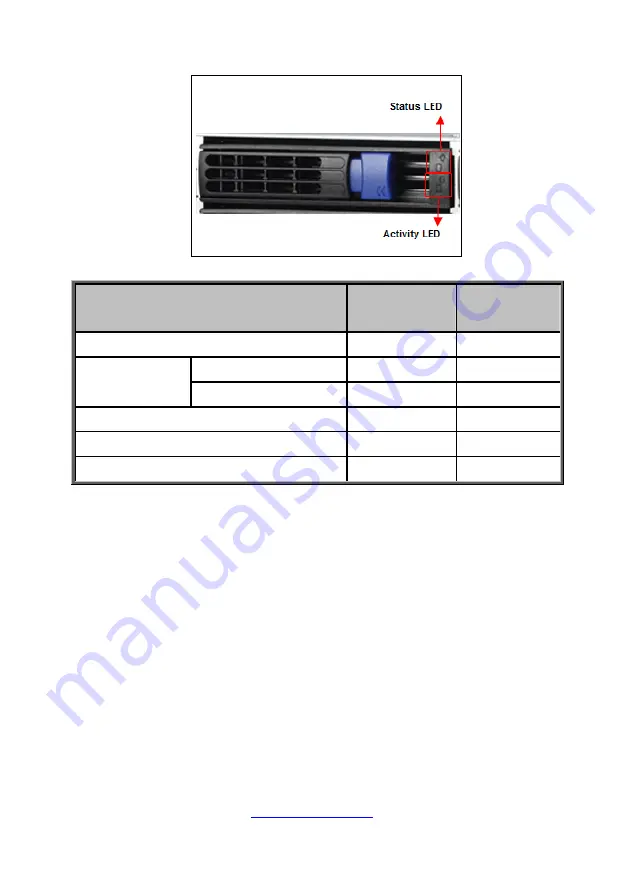
HDD LED


HDD Status


Status LED   

Color: Amber


Activity LED 

Color: Green


No Driver Present or power disconnected


OFF


OFF


No Activity


OFF


ON


Driver Present


Access Activity


OFF


Blinking


HDD Fail


On Solid


OFF


Identify (Locate the HDD)


Blinking(1Hz)


x


SAS/SATA RAID Building


Blinking(4Hz)


x


Summary of Contents for B8236G70W8HR-HE

Page 1: ...1 http www tyan com GN70 B8236 Service Engineer s Manual ...

Page 2: ...2 http www tyan com ...

Page 3: ...ability or warranties relating to fitness for a particular purpose or merchantability MiTAC retains the right to make changes to produce descriptions and or specifications at any time without notice In no event will MiTAC be held liable for any direct or indirect incidental or consequential damage loss of use loss of data or other malady resulting from errors or inaccuracies of information contain...

Page 4: ...es and can radiate radio frequency energy and if not installed and used in accordance with the instruction manual may cause harmful interference to radio communications Operation of this equipment in a residential area is likely to cause harmful interference in which case the user will be required to correct the interference at his own expense Notice for Canada This Class A digital apparatus compl...

Page 5: ...s an introduction to the TYAN GN70 B8236 barebones standard parts list describes the external components gives a table of key components and provides block diagram of the system Chapter2 Covers procedures on installing the CPU memory modules and hard drives Chapter3 Covers removal and replacement procedures for pre installed components Appendix List the cable connection and FRU part tables for ref...

Page 6: ... the purpose of this pin If your outlet does not support this kind of plug contact your electrician to replace your obsolete outlet Do not place anything on the power cord Place the power cord where it will not be in the way of foot traffic Follow all warnings and cautions in this manual and on the unit case Do not push objects in the ventilation slots as they may touch high voltage components and...

Page 7: ...ymbols on Equipment Caution This symbol indicates a potential hazard The potential for injury exists if cautions are not observed Consult equipment documentation for specific details Warning This symbol indicates the presence of hazardous energy circuits or electric shock hazards Refer all servicing to qualified personnel Warning This symbol indicates the presence of a hot surface or hot component...

Page 8: ...knees bent Equipment Racks To avoid injury or damage to the equipment Observe local occupational health and safety requirements and guidelines for manual materials handling Do not attempt to move a rack by yourself a minimum of two people are needed to move a rack Do not attempt to move a fully loaded rack Remove equipment from the rack before moving it Do not attempt to move a rack on an incline ...

Page 9: ... install the Model in a rack do not place equipment on top of the unit It will cause restricted airflow and might cause damage to the equipment Make sure the product is properly matted with the rails Products that are improperly matted with the rails might be unstable Verify that the AC power supply branch circuit that provides power to the rack is not overloaded This will reduce the risk of perso...

Page 10: ...ry to temperatures higher than 60 C 140 F The system battery is not replaceable If the battery is replaced by an incorrect type there is danger of explosion Replace the battery only with a spare designated for your product Do not attempt to recharge the battery Dispose of used batteries according to the instructions of the manufacturer Do not dispose of batteries with the general household waste T...

Page 11: ...nts Do not use conductive tools that could bridge live parts Use gloves when you remove or replace system components they can become hot to the touch If the product sustains damage requiring service disconnect the product from the AC electrical outlet and refer servicing to an authorized service provider Examples of damage requiring service include The power cord extension cord or plug has been da...

Page 12: ...http www tyan com 12 ...

Page 13: ...8 1 5 4 Jumpers Connectors 29 1 5 5 System Block Diagram S8236 30 1 5 6 Internal View 31 Chapter 2 Setting Up 33 2 0 1 Before you Begin 33 2 0 2 Work Area 33 2 0 3 Tools 33 2 0 4 Precautions 34 2 1 Installing Motherboard Components 35 2 1 1 Removing the Chassis Cover 35 2 1 2 Removing the Riser Card Brackets 37 2 1 3 Installing the CPU and Heatsink 38 2 1 4 Installing the Memory 41 2 1 4 Installin...

Page 14: ...d 61 3 5 Replacing the Power Distribution Board 62 3 6 Replacing the Front Panel Board 63 3 6 1 Front Panel Board Specifications 65 3 6 2 FPB LED and Connector Pin Definition 66 3 7 Replacing the System Fan 68 3 8 Replacing the Fan Backplane Board 70 3 8 1 Fan BP Board Specifications 73 3 8 2 Fan BP Board LED Definitions 73 3 9 Replacing the HDD Backplane Board 74 3 9 1 HDD BP Board Specifications...

Page 15: ...and 64 bit computing high bandwidth memory design and lightning fast PCI E bus implementtation The GN70 B8236 not only empowers your company in nowadays IT demand but also offers a smooth path for future application usage TYAN also offers the GN70 B8236 in a version that can support up to eight 3 5 or 2 5 hot swap hard drives The GN70 B8236 uses TYAN s latest chassis featuring a robust structure a...

Page 16: ...EDs 1 PWR 1 ID 1 Warning 3 LAN Front Panel I O Ports 2 USB ports Type Q ty 2 5 or 3 5 Hot Swap 8 External Drive Bay Supported HDD Interface SATA II 3 0Gb s SAS 6 0Gb s System Cooling Configuration FAN 8 6cm fans Type EPS1U Efficiency PFC 80 plus gold Redundancy 1 1 Input Range Full range AC 100 240V Frequency 60 Hertz Power Supply Output Watts 770W or 700W Processor Supported CPU Series AMD 45nm 8...

Page 17: ...channel 4 Channels per CPU Memory Memory voltage 1 5V or 1 35V PCI E 3 PCI E Gen 2 x16 slots NOTE The PCIE 3 slot is for half length full height card only Pre install TYAN Riser Card 1 M2201 L16 2F PCI E x16 2U riser card left 2 M2202 R16 2F PCI E x16 2U riser card right Expansion Slots Max HBA Dimension H x L 6 111 15mm x 167 65mm FH HL Port Q ty 3 LAN Controller Intel 82574L Intel 82576EB Connec...

Page 18: ...2050 AST2050 IPMI Feature IPMI 2 0 compliant baseboard management controller BMC Supports storage over IP and remote platform flash BIOS update Server Management AST2050 iKVM Feature 24 bit high quality video compression Dual 10 100 Mb s MAC interfaces Brand ROM size AMI 4MB BIOS Feature Plug and Play PnP PCI2 3 WfM2 0 SMBIOS2 3 PXE boot ACPI 2 0 power management Power on mode after power recovery...

Page 19: ...es Barebone 1 GN70B8236 Barebone Manual 1 MB User s manual 1 BB User s manual Installation CD 1 TYAN installation CD Heatsink Cooler 2 G34 CPU heatsinks Rail kit 1 CRAL 0031 sliding rail kit for KGT24 KGT62 Mounting Ear 1 mounting ear kit Package Contains Cable Power Cord 2 CCBL 0310 US type power cord 2 CCBL 0300 EU type power cord Optional accessories Peripheral 1 CDVD 0060 slim type DVD ROM ...

Page 20: ...t and undamaged The product should arrive packaged as illustrated below 1 4 1 Box Contents Component Description 2U chassis 8 hot swap HDD bays TYAN S8236 system board pre installed 1 1 ERP1U hot swap 770W RPSU Delta 1 1 ERP1U hot swap 700W RPSU Samsung 8 System fan M1601T70 D PDB Power Distribution Board pre installed M1245G70 BP6 8 SATA SAS HDD Backplane Board pre installed ...

Page 21: ...http www tyan com 21 M1709G70 FPB pre installed M2201 L16 2F riser card pre installed M2202 R8 2F riser card pre installed ...

Page 22: ... or browse to TYAN s website for service http www tyan com The web site also provides information of other TYAN products as well as FAQs compatibility lists BIOS settings etc TYAN Motherboard Drive CD Heatsink x 2 HDD Screw Pack 12 pcs Rail x 2 DVD Bracket Kit DVD Cable Kit Ventilation Bracket GPU Cable ...

Page 23: ...http www tyan com 23 SGCC Bracket_L SGCC Bracket_R AC Power Cord 125V US AC Power Cord 250V Europe Barebone Manual Mainboard Manual Addendum for China Use Only ...

Page 24: ...roduct The following views show you the product 1 5 1 System Front View 1 Ears 2 3 5 HDD bays 3 USB Ports 4 ID Button 5 NMI Button 6 RESET Button 7 NIC1 NIC2 NIC3 8 ID LED 9 Warning LED 10 BMC LED reserved 11 Power On OFF Button with LED ...

Page 25: ...off Blinking Green LAN active On Green LAN linked NIC1 off off LAN not linked Blinking Green LAN active On Green LAN linked NIC2 off off LAN not linked Blinking Green LAN active On Green LAN linked NIC3 off off LAN not linked On Red Fan fail Over temperature Over voltage Warning LED Off Off No failure On Blue System identified ID LED Off Off System not identified ...

Page 26: ...ED Color Amber Activity LED Color Green No Driver Present or power disconnected OFF OFF No Activity OFF ON Driver Present Access Activity OFF Blinking HDD Fail On Solid OFF Identify Locate the HDD Blinking 1Hz x SAS SATA RAID Building Blinking 4Hz x ...

Page 27: ...On Green 10Mb 100Mb 1000Mb linked Blinking Green 10Mb 100Mb 1000Mb activity RJ 45 Activity left Disabled Flash Green No LAN linked On Amber 1000Mb linked On Green 100Mb linked RJ 45 Linkage Right Disabled Off 10Mb mode or No LAN linked NOTE Left and Right are viewed from the rear panel ID LED LED State Color Description On Blue System identified ID LED Off Off System not identified ...

Page 28: ...www tyan com 28 1 5 3 Motherboard S8236 Layout The diagram is representative of the latest board revision available at the time of publishing The board you receive may not look exactly like the above diagram ...

Page 29: ... J32 LAN3 Active LED Header J53 HDD Fault Header J59 IPMB Header JP1 JP2 COM2 Function Select Jumper JP3 Clear CMOS Jumper JP6 Front Panel ID LED Button JP7 Chassis Intrusion Header LED1 ID LED LED2 SAS Flash Ready Amber LED3 SAS HD Fault LED Amber LED4 Power On LED Green LED5 Standby LED Green LED6 SAS Error LED Amber LED7 SAS Heart Beat LED Green LED8 BMC Heart Beat LED Green Jumper Legend OPEN ...

Page 30: ...http www tyan com 30 1 5 5 System Block Diagram S8236 ...

Page 31: ...tyan com 31 1 5 6 Internal View With Riser Card Brackets 1 3 5 HDD cage underneath 2 SAS SATA HDD Backplane Board 3 System Fan Unit 4 Power Distribution Board 5 PCI E Riser Card Bracket 6 Power Supply underneath ...

Page 32: ...http www tyan com 32 Without Riser Card Brackets 1 3 5 HDD cage underneath 2 SAS SATA HDD Backplane Board 3 System Fan Unit 4 Power Distribution Board 5 Power Supply underneath ...

Page 33: ...nts separated Putting all small components in separate containers prevents them from becoming lost Adequate lighting and proper tools can prevent you from accidentally damaging the internal components 2 0 3 Tools The following procedures require only a few tools including the following A cross head Phillips screwdriver A grounding strap or an anti static pad Most of the electrical and mechanical c...

Page 34: ...id touching motherboard components IC chips connectors memory modules and leads The motherboard is pre installed in the system When removing the motherboard always place it on a grounded anti static surface until you are ready to reinstall it Hold electronic circuit boards by the edges only Do not touch the components on the board unless it is necessary to do so Do not flex or stress circuit board...

Page 35: ...nents on to the motherboard including CPUs memory modules HDD and PCI E cards 2 1 1 Removing the Chassis Cover Follow these instructions to remove the GN70 B8236 chassis cover 1 Unscrew the rear top cover on the back side 2 Unscrew the front top cover and pull the latches aside to lift up the top cover ...

Page 36: ...http www tyan com 36 3 Slide the rear top cover out ...

Page 37: ...n com 37 2 1 2 Removing the Riser Card Brackets Follow these instructions to remove the PCI E Riser Card Brackets 1 Loose four thumb screws to release the PCI E Riser Card Brackets 2 Lift up the Riser Card Brackets ...

Page 38: ...CPU and Heatsink Follow the steps below on installing CPUs and CPU heatsinks 1 Locate the CPU sockets 2 Pull the lever slightly away from the socket and then push it to a fully open position 3 Push the CPU socket cover to a fully open position ...

Page 39: ...yan com 39 4 Take out the protection cap 5 Place the CPU into the socket and make sure that the gold arrow is located in the right direction 6 Close the CPU socket cover and press the lever down to secure the CPU ...

Page 40: ...http www tyan com 40 7 Position the heatsink on top of the CPU and secure it with 2 screws 8 Repeat the procedures mentioned earlier to install the second CPU and heatsink ...

Page 41: ...therboard 2 Press the memory slot locking levers in the direction of the arrows as shown in the following illustration 3 Align the memory module with the slot When inserted properly the memory slot locking levers lock automatically onto the indentations at the ends of the module Follow the recommended memory population table to install the other memory modules ...

Page 42: ...http www tyan com 42 Memory Population Option Table The following pictures show common types of DDR3 memory modules ...

Page 43: ...U1_DIMM 12 C1 CPU1_DIMM 13 B0 CPU1_DIMM 14 B1 CPU1_DIMM 15 A0 CPU1_DIMM 16 A1 NOTE 1 indicates a populated DIMM slot 2 Paired memory installation for Max performance 3 Populate the same DIMM type in each channel specifically Use the same DIMM size Use the same of ranks per DIMM 4 Dual rank DIMMs are recommended over single rank DIMMs 5 Un buffered DIMM can offer slightly better performance than re...

Page 44: ...MHz SR and DR n a 1066MHz 1066MHz SR and DR SR and DR 1066MHz 1333MHz SR and DR n a 1066MHz 1333MHz SR and DR SR and DR Notes U DIMM can support up to 4GB sized DIMM s Maximum of 8GB per channel SR and DR UDDR3 module support only x8 DRAM module support only SR and DR 1 35v Memory MAX speed of 1066MHz in a dual channel configuration SR and DR 1 5v Memory MAX speed of 1333MHz in a dual channel conf...

Page 45: ...R n a 1066MHz QR SR DR and QR n a 1333MHz SR and DR n a n a 1333MHz QR n a Notes RDIMM can support up to 16GB sized DIMM s SR and DR Memory has a MAX amount of 16GB per channel SR and DR 1 35v Memory MAX speed of 1066MHz in a dual channel configuration SR and DR 1 5v Memory MAX speed of 1333MHz in a dual channel configuration QR Memory has a MAX amount of 32GB per channel QR 1 35v Memory MAX speed...

Page 46: ... to eight 8 3 5 or 2 5 hard drives Follow these instructions to install a hard drive Warning Always install the hard disk drive to the chassis after the chassis is secured on the rack 1 Press and hold the locking lever latch to pull the locking lever open 2 Slide the HDD tray out ...

Page 47: ...http www tyan com 47 Option A for 2 5 hard drives 3 Place a 2 5 hard drive into the HDD tray and use 4 screws to secure the HDD Option B for 3 5 hard drives 4 Unscrew the drive bracket from the HDD tray ...

Page 48: ...http www tyan com 48 5 Place a 3 5 hard drive into the drive tray and use 6 screws to secure the HDD 6 Reinsert the HDD tray into the chassis and press the locking lever to secure the tray ...

Page 49: ...r Card Brackets A power cable 2x3p 2x4p is required for GPU cards Follow these instructions to install PCI E cards 1 Unscrew the PCI E slots to take out the PCI brackets 2 Insert the PCI E cards and securely screw as shown 3 Repeat the same procedures for the second and third Riser Card Brackets ...

Page 50: ...http www tyan com 50 ...

Page 51: ...the TYAN GN70 B8236 into an industry standard 19 rack NOTE Before mounting the TYAN GN70 B8236 in a rack ensure that all internal components have been installed and that the unit has been fully tested However to make the installation easier we suggest that you remove all HDD trays before you insert the chassis to the rack 1 Position the rear of the sliding rail to the rear side of the rack Make su...

Page 52: ...52 http www tyan com 2 Repeat the same procedures for the front end of the rail Front 3 Push the locking latch to secure the rail to the rack Repeat the same procedures for the other rail Left Right ...

Page 53: ...e to its full length push the locking tab of the rail upward and then the rail can slide freely There are three holes on each rail which are used to hook and secure the chassis 5 Align the studs on the chassis with the holes on the rails and make sure the chassis is securely hooked ...

Page 54: ...http www tyan com 54 6 Push the chassis back into the rack 7 The installation is now complete ...

Page 55: ...he Server from a Rack Follow these instructions to remove the TYAN GN70 B8236 from an industry standard 19 rack 1 Push the ears to pull the chassis forward 2 Push forward the locking tabs on both rails to unhook the chassis from the rails ...

Page 56: ...56 3 Follow the steps described earlier in reverse to remove the chassis from the rack NOTE To avoid injury it is strongly recommended that at least two people lift the TYAN GN70 B8236 to hook on or unhook from the rails ...

Page 57: ...pter explains how to replace the pre installed components including the S8236 Motherboard M1709G70 FPB Front Panel Board PCI E Riser Card M1245G70 BP6 8 SATA SAS HDD Board System Fan and Power Supply Unit etc 3 2 Disassembly Flowchart The following flowchart outlines the disassembly procedure ...

Page 58: ...Motherboard Components Follow these instructions to replace motherboard components including the motherboard 3 4 1 Replacing PCI E Riser Card Cards The GN70 B8236 has three pre installed PCI E 16 riser cards Follow the instructions below to disassemble the M2201 L16 2F and M2202 F16 2F PCI E riser cards 1 Unscrew to take out the PCI E cards 2 Unscrew the M2201 L16 2F riser card to replace a new on...

Page 59: ...http www tyan com 59 3 Repeat the same procedures for the second and third Riser Card Brackets 4 Unscrew the M2202 F16 2F riser card to replace a new one if necessary ...

Page 60: ... replacing the motherboard or certain components remove cables connected to the motherboard Follow these instructions to remove all cables 1 Disconnect the power and PSMI cables 2 Disconnect the Mini SAS USB fan control and front panel cables 3 Disconnect the power cable ...

Page 61: ...ll of the aforementioned cables follow the instructions below to remove the motherboard from the chassis 1 Remove the heatsinks and processors if installed 2 Remove the nine screws securing the motherboard to the chassis 3 Carefully lift the motherboard from the chassis ...

Page 62: ...tyan com 62 3 5 Replacing the Power Distribution Board Follow these instructions to replace the M1601T70 D PDB power distribution board 1 Disconnect all cables 2 Unscrew to replace a new power distribution board ...

Page 63: ... these instructions to replace the M1709G70 FPB Front Panel Board 1 Unscrew to release the Front Panel Board Module 2 Push the Front Panel Board Module forward 3 Disconnect the Front Panel Control and USB cables 4 Unscrew the Front Panel Board to replace a new one ...

Page 64: ...http www tyan com 64 5 Follow the steps described earlier in reverse to reinstall the Front Panel Board ...

Page 65: ...B Connectors One 2x15 pin header for front panel connector of motherboard and HDD backplane board LEDs Power On Off LED Color Green after power on ID LED Color Blue Warning IPMI LED Dual Color Yellow Warning Green Normal Push buttons RESET button ID button Power On Off button with Power On Off LED ...

Page 66: ... on the server by clicking the Chassis Locate LED key ID LED Off Off System not identified For more information on the Chassis Locate LED please visit our Web site for the latest Pilot II Software Configuration Guide Front Panel Connector J3 Definition Pin Pin Definition PW_LED 1 2 VCC Key 3 4 ID_LED PW_LED 5 6 ID_LED HD LAN3_LED 7 8 SYS_FAULT1 HD LAN3_LED 9 10 SYS_FAULT2 PWR_SW 11 12 LAN1_LED PWR...

Page 67: ...http www tyan com 67 USB Connector J1 Definition Pin Pin Definition VCC 1 2 VCC USB1 3 4 USB2 USB1 5 6 USB2 GND 7 8 GND KEY 9 10 GND ...

Page 68: ...om 68 3 7 Replacing the System Fan Follow these instructions to replace the system fan 1 Press the latch in the direction as shown to lift up the fan from cage 2 Take out the fan unit 3 Loose the screws on both sides ...

Page 69: ...an com 69 4 Push the latch in the direction as the arrow shown to release the fan from the iron holder 5 Remove the iron holder to replace a new fan 6 After replacing a new one put the fan unit back into the cage ...

Page 70: ...8 Replacing the Fan Backplane Board Follow these instructions to replace the Fan Backplane Board in your system 1 Press the latch in the direction as shown to lift up the fan from cage 2 Remove all eight fans from the chassis ...

Page 71: ...http www tyan com 71 3 Disconnect all cables attached to the Fan Backplane Board 4 Use a screw driver to unscrew the Fan Module 5 Disconnect the power and fan cables 6 Lift up the Fan Module ...

Page 72: ...http www tyan com 72 7 Release the 14 screws on the Fan Backplane Board to replace a new one 8 Follow the steps described in reverse order to reinstall the fan cage ...

Page 73: ...actor 254 mm x 82 mm 4 layer PCB Integrated I O 2 1x4pin R A Power Connector 8 2x2pin Fan Connectors 1 2 x10pin Barebone Fan Connector 1 2x2pin Connector for S7015 3 8 2 Fan BP Board LED Definitions FAN Status Green LED Red LED With Fan On Off Without Fan Off On ...

Page 74: ...kplane Board 1 Refer to Section 3 8 Replacing the Fan Backplane Board for how to remove the Fan Module Disconnect the power cables attached to the HDD BP Board 2 Unscrew the HDD BP Board Remove the HDD BP Board from the hook 3 Replace a new HDD BP Board and reinstall it into the chassis following the steps in reverse ...

Page 75: ...lar Form Factor 81 8 x 436 mm 4 layer PCB Integrated I O 8 SAS HDD Connectors 2 Mini SAS Connectors to MB and RAID Card 1 2 x 4 pin Power Connector LEDs 8 HDD active LEDs 8 HDD fault LEDs PW3 Pin definition Definition Pin Pin Definition GND 1 5 12V GND 2 6 12V GND 3 7 12V GND 4 8 12V ...

Page 76: ...connected OFF OFF No Activity OFF ON Driver Present Access Activity OFF Blinking HDD Fail On Solid OFF Identify Locate the HDD Blinking 4Hz x SAS SATA RAID Building Blinking 1Hz x NOTE If the LSI 9280 l6i4e or 9260 l6i storage cards is installed the LED status will change as below Identify Locate the HDD Blinking 4Hz ON SAS SATA RAID Building Blinking Blinking ...

Page 77: ... tyan com 77 3 10 Replacing the Power Supply 1 Press and hold the latch to pull the power supply out 2 After replacing a new power supply press and hold the latch to push the power supply back into the chassis ...

Page 78: ...http www tyan com 78 NOTE ...

Page 79: ...7 SAS_2 J11 2 FAN Control Cable FAN Board M1806G70 FB Connects to Motherboard J8 J28 3 Front Panel Control Cable Front Panel Board M1709G70 FPB Connects to Motherboard J3 J23 4 USB Cable Front Panel Board M1709G70 FPB Connects to Motherboard J1 J33 5 Power Cables Power Board M1601T70 D PDB Connects to Motherboard PW1 MB PW1 PATX1 MB1 PW2 ...

Page 80: ... com 80 PATX2 MB2 PW3 J7 PSMI J31 Power Board M1601T70 D PDB Connects to FAN Board M1806G70 FB PW4 FAN BD1 PW2 PW5 FAN BD2 PW1 Power Board M1601T70 D PDB Connects to SAS SATA Backplane M1245G70 BP6 PATX8 HDD BP3 PW1 ...

Page 81: ...el Number Part Number Picture Quantity Description Power Supply DPS 770CB 471015200243 2 DELTA DPS 770CB 1U FAN PFC0612DE 7N51 336252012309 8 12000RPM 60 60 38MM 4PIN PCBA M2201 L16 2F 411794700007 1 PCI E X16 1U Riser Card PCBA M2202 R16 2F 411T41000017 2 PCI E X16 1U Riser Card ...

Page 82: ...http www tyan com 82 NOTE ...

Page 83: ...p www tyan com provides easy to access resources such as in depth Linux Online Support sections with downloadable Linux drivers and comprehensive compatibility reports for chassis memory and much more With all these convenient resources just a few keystrokes away users can easily find their latest software and operating system components to keep their systems running as powerful and productive as ...

Page 84: ...oper maintenance of products NOTE A receipt or copy of your invoice marked with the date of purchase is required before any warranty service can be rendered You may obtain service by calling the manufa cturer for a Return Merchandise Authorization RMA nu mber The RMA number should be prominently displayed on the outside of the shipping carton and the package should be mailed prepaid TYAN will pay ...

Reviews: