background image


LEAK TEST 


CAUTION BEFORE LIGHTING 


Finding and/or fixing a gas leak is NOT a “DO IT YOURSELF” procedure. 


NEVER USE THE POWER BURNER WITHOUT FIRST LEAK TESTING THE GAS 
CONNECTIONS 


WARNING: DO NOT USE AN OPEN FLAME TO CHECK FOR LEAKS. USE OF AN OPEN 
FLAME COULD RESULT IN A FIRE, EXPLOSION, AND BODILY HARM. 


DO NOT SMOKE WHILE PERFORMING THE LEAK TEST! 


To prevent fire or explosion hazard, DO NOT use or permit sources of ignition in the area while 
performing a leak test. Perform leak test outdoors only. 


Check to ensure that flexible hose do not have any cuts and wear that may affect the safety before each 
use. Only the factory supplied regulator must be used. Use only replacement regulator specified by Twin 
Eagles. 


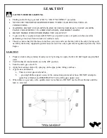
LEAK TEST 
 

1.


Prepare a leak testing solution of sudsy water by mixing in a spray bottle with half liquid soap and half 
water. 

2.


Confirm that all control knobs are in the OFF position. 

3.


Turn the main gas valve ON. 

4.


Apply leak testing solution by spraying on the pipe joints, fitting, and hose. 

5.


A gas leak is detected if, 

a.


There is a faint gas smell and/or… 

b.


…growing bubbles appear on any of the connection points and/or hose, DO NOT attempt to 
ignite Power Burner and IMMEDIATELY turn off the gas supply valve. 

6.


When there is a gas leak, call a qualified service technician. DO NOT use the Power Burner until the 
leak is corrected. 


Summary of Contents for TEPB24HG-C

Page 1: ...TWIN EAGLES POWER BURNER INSTALLATION USE CARE MANUAL MODELS TEPB24HG C SHOWN TEPB24 C P N 19239A ...

Page 2: ...s down Thank you and welcome Dante Cantal Owner and Founder FOR YOUR RECORDS Please record the product information below and refer to it when contacting TWIN EAGLES This information is found on the data nameplate located on the bottom right hand side of the body near the regulator A second label with model number and serial number is located under the right side of the front panel Remove the drip ...

Page 3: ...le voisinage de cet appareil ou de tout autre appareil THIS APPLIANCE IS FOR OUTDOOR USE ONLY If stored indoors detach and leave L P cylinder outdoors CE APPARIEL EST POUR UTILISATION à L EXTÉRIEUR SEULEMENT Si l appareil est entreposé à l interieur enlever les bouteilles et les laisser à l extérieur B E F O R E L I G H T I N G 1 Read instructions before lighting 2 Remove cover during lighting 3 I...

Page 4: ...r to this appliance Keep the ventilation openings of the cylinder enclosure free and clear from debris 8 Check all gas connections for leaks with soapy water solution and brush Never use an open flame Reference page 6 for leak test procedure 9 Check flexible hoses for cuts and wear that may affect the safety before each use 10 Never use the Power Burner in a windy area 11 Never use the Power Burne...

Page 5: ...DJUSTMENT ELECTRICAL REQUIREMENTS CUTOUT DIMENSIONS OPERATING INSTRUCTIONS o BEFORE LIGHTING o HOW TO LIGHT o MATCH LIGHTING INSTRUCTIONS CLEANING AND MAINTENANCE o STAINLESS STEEL o GRATES o BURNER o SPIDER AND INSECT WARNING o BURNER INSTALLATION CHECK o WIRING DIAGRAM REPLACEMENT PARTS o EXPLODED VIEW o REPLACEMENT PARTS LIST o TROUBLE SHOOTING GUIDE o LIMITED PRODUCT WARRANTY o WARRANTY REGIST...

Page 6: ...ard and mail it to the indicated address Power burner Accessories TEPB24 BN TEPB24 BL TEPB24HG BN TEPB24HG BL Grate Round Stainless Steel 1 1 Grate Round Middle Stainless Steel 1 1 Grate Power Burner Optional heavy duty 1 1 Regulator NG NG Power burner only PRE INSTALLED Regulator LP LP Power burner only PRE INSTALLED Specifications Value Counter Opening Height 11 50 Counter Opening Width 22 00 Co...

Page 7: ...ÉGAGEMENT DE TOUTE CONSTRUCTION COMBUSTIBLE Il faut maintenir une distance minimum de 12 po 30 48 cm sur les côtés et de 6 po 15 24 cm sur l arrière du gril par rapport aux constructions combustibles verticales adjacentes CLEARANCE TO NONCOMBUSTIBLE CONSTRUCTION A minimum clearance of 1 from the back of the Power Burner above cooking surface to non combustible construction is required A minimum of...

Page 8: ... COME IN CONTACT WITH ANY HOT SURFACE OF THE POWER BURNER NEVER CONNECT THE POWER BURNER TO AN UNREGULATED GAS SUPPLY L P GAS SAFETY REQUIREMENT The LP gas supply cylinder must be constructed and marked in accordance with the Specifications for LP gas Cylinders of the U S Department of Transportation D O T or the National Standards of Canada CAN CSA B339 Cylinders Spheres and Tubes for the Transpo...

Page 9: ...tion in a built in enclosure 1 At least one ventilation opening shall be provided on the exposed exterior side of the enclosure located within 5 in 1 27mm of the top of the enclosure and unobstructed The opening s shall have a total free area of not less than 1 in lb 14 2 cm kg of stored fuel capacity 2 At least one ventilation opening shall be provided on the exposed exterior side of the enclosur...

Page 10: ...ot use with a 20 lb LP cylinder Make sure that the regulator is set for natural gas To check remove the brass hex cap You will find the conversion plastic pin attached to the cap to the underside of the cap If the disc 1 2 in diameter of the pin is close to the cap then the regulator is set for natural gas If the disc is at the tip of the pin away from the brass cap the regulator is set for system...

Page 11: ...ay affect the safety before each use Only the factory supplied regulator must be used Use only replacement regulator specified by Twin Eagles LEAK TEST 1 Prepare a leak testing solution of sudsy water by mixing in a spray bottle with half liquid soap and half water 2 Confirm that all control knobs are in the OFF position 3 Turn the main gas valve ON 4 Apply leak testing solution by spraying on the...

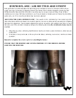
Page 12: ...of air is controlled by a sheet metal cup at the inlet of the burner called an air shutter It is locked in place by a set screw which must be loosened prior to lighting the burner for adjustment The air shutter adjustment screws are accessible with a phillips screwdriver Loosen the lock screw of the air shutter Adjust according to the following directions Be careful as the burner may be very hot I...

Page 13: ...manner Contact the manufacturer for repair 4 Do not let cord hang over the edge or touch hot surfaces 5 Do not us an outdoor cooking gas appliance for purposes other than intended 6 When connecting first connect plug to the outdoor cooking gas appliance then plug appliance into outlet 7 Use only Ground Fault Interrupter GFI protected circuit with this outdoor cooking gas appliance 8 Never remove t...

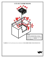
Page 14: ...9 CUT OUT DIMENSIONS WARNING The Power Burner must be installed in a NON COMBUSTIBLE ENCLOSURE ONLY NOTE IT IS RECOMMENDED TO BUILD THE ENCLOSURE FOR THE POWER BURNER 6 12 LOWER THAN THE COUNTERTOP ...

Page 15: ...LIGHT THE POWER BURNER S BURNER Lighting the Power Burner 1 Open the gas supply shut off valve 2 Push in the knob and verify that the hot surface igniter glows If the igniter does not glow verify for proper power supply Reference page 8 for electrical requirements 3 Once the glowing is verified for 5 seconds simultaneously push in and turn the knob counter clock wise to the biggest flame marking o...

Page 16: ...periods of time However the conditions outlined above along with neglect can lead to surface corrosion or rust ATTENTION Do not allow food particles or grease to be left on the surfaces of the Power Burner These can attract rodents which are unsanitary and are likely to cause physical damage by chewing on the wiring which can cause permanent damage to the electrical components Specks of grease can...

Page 17: ...logged ports Make sure the burner is dry before installing it back to the Power Burner DRIP PAN The drip pan collects grease liquid and fallen food particles Allow the pan and its contents to cool before cleaning Slide the pan out and wipe it clean Make sure the drip pan is fully inserted back into the Power Burner It is highly recommended to clean the pan after every use to avoid any possibility ...

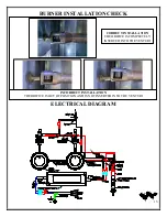
Page 18: ...RNER INSTALLATION CHECK ELECTRICAL DIAGRAM CORRECT INSTALLATION THE ORIFICE IS COMPLETELY INSERTED INTO THE VENTURI INCORRECT INSTALLATION THE ORIFICE IS OUT OF POSITION AND IS NOT INSERTED INTO THE VENTURI ...

Page 19: ...14 EXPLODED VIEW ...
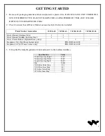
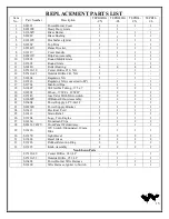
Page 20: ... 1 1 17 S12762 Manifold Pipe 1 1 1 1 18 S12407 SS Flexible Tubing 375 x 7 2 2 2 2 19 S12601 Elbow 375CC x 125FIP 2 2 2 2 20 S15149 Gas Valve With Microswitch 2 2 2 2 21 S12688Y IR Burner Elbow Assembly 2 2 2 2 22 S16404 Power Supply LPV 60 12 1 1 1 1 23 S26366Y Power Supply Bracket 1 1 1 1 24 S16111 Electrical Cord 1 1 1 1 25 S16112 Strain Relief 1 1 1 1 26 S13204 Logo Twin Eagles 1 1 1 1 27 S1416...

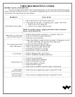
Page 21: ...utter for proper adjustment 3 Check any source of gas leak Low heat generated with knob in HI position 1 Check if the problem is isolated to only one burner If it appears so clean the orifice and burner clearing ports of any obstruction 2 Check for any bent or kinked fuel hose 3 Check if the air shutter is properly adjusted 4 Check for proper gas supply and pressure 5 Pre heat Power Burner for 15 ...

Page 22: ...surface scratches weather and atmospheric related staining and minor surface rust and oxidation which are normal conditions and are to be expected with any outdoor product This warranty does not apply to damages resulting from negligence alteration misuse abuse accident natural disaster loss of electrical power to the product for any reason improper installation or improper operation unauthorized ...

Page 23: ...62 802 3488 or fax 562 802 3391 Mailing address Twin Eagles Inc 13259 East 166th Street Cerritos CA 90703 Visit us at www twineaglesgrills com Please provide Model number Serial Number Date of Purchase A description of the problem THIS WARRANTY REGISTRATION CARD MUST BE RETURNED WITHIN THIRTY DAYS OF PURCHASED TO PROPERLY ACTIVATE YOUR WARRANTY THIS INFORMATION IS FOR INTERNAL USE ONLY OR YOU MAY ...

Page 24: ...Customer Service ATTN Warranty Department 13259 East 166th Street Cerritos CA 90703 Fax no 562 802 3391 Place Postage Here Cut Here ...

Reviews: