TCF&B ES-52
4
A
DIA
B
RBO
RBR
B
B
B
A
B
A
B
A
SWSI
DWDI
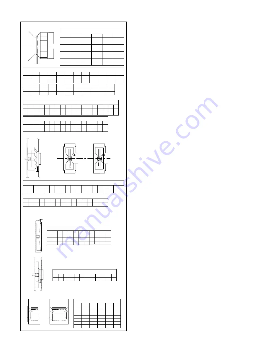
Figure 6. Wheel-Funnel Overlap
Note: On sizes 905-911 wheel is to be centered in housing.
RBW – Center wheel in housing.
RBO / RBR Wheel Placement
Size 913
915
917
919
921
923
926
929
933
937
941
945
949
954
960
B
0.53 0.53 0.59 0.69 0.78 0.88 0.97 1.03 1.22 1.38 1.56 1.69 1.81 1.88 2.16
*Use dimension “B” for positioning wheel on SSI and TSL.
BC, BCS, TSL & BAF SWSI Wheel Placement
Size
122
135
150
165
182
200
222
245
270
300
330
A
12.25
13.50
15.00
16.50
18.25
20.00
22.25
24.50
27.00
30.00
33.00
B
0.32
0.34
0.38
0.44
0.56
0.63
0.69
0.75
0.88
0.97
1.06
APF – Straight Bore Hubs Wheel Placement
Size
121
141
161
181
201
221
251
281
321
351
391
441
491
551
631
711
791
A
13.00 14.13 16.16 18.44 19.94 22.78 25.06 28.25 31.81 35.81 39.81 44.56 50.06 55.75 63.69 71.69 79.63
B
0.25 0.25 0.25 0.31 0.31 0.31 0.50 0.50 0.56 0.63 0.63 0.75 0.78 0.81 1.03 1.28 1.38
Size
365
402
445
490
542
600
660
730
807
890
A
36.50
40.25
44.50
49.00
54.25
60.00
66.00
73.00
80.75
89.00
B
0.94
1.03
1.13
1.25
1.38
1.56
1.69
1.88
2.09
2.28
HIB, RTF, HRT Wheel Placement
Size
A
B
Size
A
B
180
20.50
0.31
400
45.25
0.69
200
22.50
0.34
450
50.00
0.75
220
25.00
0.38
490
55.13
0.81
240
27.50
0.44
540
61.00
0.91
270
30.38
0.47
600
67.50
1.00
300
33.50
0.50
660
74.25
1.13
330
37.00
0.56
730
82.00
1.22
360
41.00
0.63
800
90.75
1.34
fan. Every switch should have the ability to be “locked-off”
by the service person and the key to be retained by this per-
son to prevent accidental power of the fan while service is
in process.
Operation Checklist
Verify that proper safety precautions have been followed:
Electrical power must be locked off.
Check fan mechanism components:
System connections are properly made and tightened.
Bearings are properly lubricated.
Wheel, drives and fan surfaces are clean and free of
debris.
Rotate the impeller by hand to verify it has not shifted
in transit.
Check wheel/funnel overlap. See Figure 6.
Drives on correct shafts (not reversed).
Check position of guards to prevent rubbing.
Check fan electrical components:
Motor is wired for proper supply voltage.
Motor was properly sized for power and rotational
inertia of rotating assembly.
Motor is properly grounded.
All leads are properly insulated.
Trial “bump”:
Turn on power just long enough to start assembly
rotating.
Check rotation for agreement with rotation arrow.
Does the assembly make any unusual noise?
(See Figure 7)
Check drive alignment and tension. Does this meet
with drive manufacturer’s recommendations?
Correct any problems which may have been found.
(Follow safety guidelines - shut power off). Perform
checklist again until unit is operating properly.
Run unit up to speed.
Verify fastener tightness. These may have loosened during
shipment or installation.
Set screws attaching wheel hub to shaft.
Set screws in drive sheaves or coupling.
Nuts on inlet funnel.
Nuts and bolts holding motor.
Nuts holding housing frame to base and base to
ground.
Nuts on accessories including shaft seal, access
doors and pie-splits.
Bolts in taper-lock bushings.
Grease line connections.
After one week of operation, check all nuts, bolts and set
screws and tighten if necessary.
Maintenance of Fans
This section contains general maintenance instructions for
your Twin City Fan & Blower unit. For specific information
about maintenance of components, particularly for special
application fans, see the attached documents.
General Motor Maintenance
The three basic rules of motor maintenance are:
1. Keep the motor clean.
2. Keep the motor dry.
3. Keep the motor properly lubricated.
Keeping motors and windings clean is important
because dirt and dust serve as thermal insulators. Heat nor-
mally dissipated by the motor is trapped causing overheat-
ing and/or premature failure. Blow dust and dirt out of wind-
ings and off the motor periodically. Use low pressure (50
psig) airstream so that winding damage does not occur.
Keep the area surrounding the motor open so the air can cir-
culate through the motor cooling fan. Follow normal mainte-
HIB, RTF, HRT, BC, BCS, TSL, BAF, SSI & APF
RBA, RBO, RBR & RBW
MBW, MBO, MBR
BCN
A
FC Wheel Placement
Size
A
B
Size
A
B
10.5
0.47
0.69
30
0.75
4.38
12
0.25
1.88
33
0.81
5.00
15
0.44
2.19
36
0.75
5.00
18
0.50
2.25
39
1.06
6.38
21
0.69
2.88
42
1.69
7.50
24
0.81
3.00
48
1.50
7.13
27
0.69
3.13
54
1.00
10.50
RBA
RBA Wheel Placement
Size 907
909
911
913
915
917
919
921
923
926
929
933
937
941
945
949
954
960
A
0.25 0.38 0.47 0.53 0.59 0.69 0.69
0.0
0.0
0.0
0.0
0.0
0.0
0.0
0.0
0.0
0.0
0.0
FC
APF – Taper Lock Hubs Wheel Placement
Size
121
141
161
181
201
221
251
281
321
351
391
441
491
551
631
A
13.00 14.13 16.16 18.44 19.94 22.78 25.06 28.25 31.81 35.81 39.81 44.56 50.06 55.75 63.69
B
0.25 0.25 0.25 0.31 0.31 0.31 0.50 0.50 0.56 0.63 0.63 0.75 0.78 0.81 1.03
GAP
MBW, MBO, MBR Wheel Placement
Size 196
224
252
280
308
336
365
421
477
533
589
MBW 0.50 0.44 0.38 0.25 0.38 0.44 0.56 0.63 0.75 0.75 0.88
MBO 0.50 0.44 0.38 0.25 0.38 0.44 0.56 0.63 0.75 0.75 0.88
MBR 0.25 0.25 0.25 0.25 0.25 0.38 0.50 0.69 0.81 0.94 1.00
BCN Wheel Placement
Size 270
300
330
365
402
445
490
542
600
660
730
A
0.09 0.09 0.13 0.13 0.13 0.16 0.16 0.19 0.22 0.22 0.25
A


