


2
Twin City Engineering Supplement 895
cause premature belt or drive replacement. If burrs are
found, use fine emery cloth or a stone to remove them.
Be careful that dust does not enter the bearings.
Check sheaves for wear. Excessive slippage of belts
on sheaves can cause wear and vibration. Replace worn
sheaves with new ones. Carefully align sheaves to avoid
premature sheave failure.
Inspect the belts for wear. If fraying or other wear is
observed to be mostly on one side of the belts, the
drives may be misaligned. Reinstall the drives according
to the following instructions:
1. Slip (do not pound) proper sheave onto corresponding
shaft.
CAUTION:
Placing fan sheave on motor can over-
speed wheel and cause structural failure.
2. Align sheaves with straightedge extended along
sheaves, just making contact in two places on out-
side perimeters of both sheaves.
3. Tighten sheave bolts (or setscrews if appropriate).
Table 1 can be used to determine the amount of
torque required.
4. Install a matched set of belts. Adjust the motor posi-
tion to obtain slack, install, and tighten belts. Using
a pry bar will damage belts.
5. Tighten belts to proper belt tension. Ideal tension is
just enough so that the belts do not slip under peak
load. When using drive tensioning data supplied by
V-belt drive manufacturers, new belts can be tensioned
to a value 50% greater than for normal operation. This
will reduce retensioning requirements after break-in.
Recheck sheave alignment after tensioning.
6. After initial installation of belts, recheck belt tension
again after a few days. (New belts require a break-in
period of operation.)
7. When replacing belts, replace the entire set. After initial
replacement and tensioning, recheck belt tension after
a few days. (New belts require a break-in period of
operation.) Never use belt dressing on any belts.
8. Fans that have motors and drives mounted at the
factory are trim balanced prior to shipment. This is
not possible on units that are shipped without motors
and drives. The addition of drive components in the
field can create unbalance forces. Twin City Fan &
Blower recommends final balancing of the unit after
the drive components are installed. Failure to do so
may void the warranty.
Motor Support Adjustment
Two different types of motor mounts, post and saddle,
are used on TSL Inline Centrifugal and QSL Mixed Flow
fans. Which mount to use depends on the size of the fan
and motor.
On the post type motor mount, the motor plate is
supported on four threaded rods. Belt tension is adjust-
ed by loosening the four nuts on top of the motor plate
and raising the motor plate by adjusting the four nuts
underneath it. The top nuts should then be tightened to
hold the motor plate in place.
On the saddle type motor mount, the motor pivots
on one side and adjustment of belt tension is achieved
by loosening the nuts on top of the motor plate on the
other side, then raising the motor plate by adjusting the
nuts underneath the motor plate. The nuts on top of the
motor plate should again be tightened to hold the motor
plate in place. Several holes are provided on the pivot
side, and the pivot point can be raised for gross belt
adjustment. If this adjustment is made, however, the
motor plate should be as parallel as possible to the fan
centerplane. Care should be taken to maintain drive
alignment and proper belt tension.
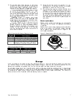
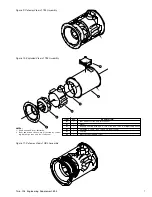
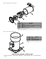
Bearing Maintenance
Proper lubrication of the fan drive bearings helps assure
maximum bearing life. All fans are equipped with decals
indicating relubrication intervals for normal operating
conditions. See Figures 2, 3 and 4 for typical lubrication
data. However, every installation is different and the
frequency of relubrication should be adjusted accord-
ingly.
On high moisture applications, the lubrication fre-
quency may need to be doubled or tripled to adequate-
ly protect the bearings. Double the relubrication fre-
quency on fans with vertical shafts.
Observation of the conditions of the grease expelled
from the bearings at the time of relubrication is the best
guide as to whether regreasing intervals and amount of
grease added should be altered.
Greases are made with different bases. There are
synthetic base greases, lithium base, sodium base, etc.
Avoid mixing greases with different bases. They could
be incompatible and result in rapid deterioration or
breakdown of the grease. The lubrication sticker identi-
fies a list of acceptable lubricants. All bearings are filled
with a lithium-based grease before leaving the factory.
When the fans are started, the bearings may discharge
excess grease through the seals for a short period of
time. Do not replace the initial discharge because leakage
will cease when the excess grease has worked out.
Sometimes the bearings have a tendency to run hotter
during this period. There is no reason for alarm unless
it lasts over 48 hours or gets very hot (over 200°F). When
relubricating, use a sufficient amount of grease to purge
the seals. Rotate bearings by hand during relubrication.
Table 1. Tightening Torque (Ft.-Lbs.)
Tolerance: +5%
For wheel setscrews use Grade 2 values. The above torque values are for nonlubricated fasteners.
SIZE
FASTENER
TAPER BUSHINGS
GRADE 2
GRADE 5
GRADE 8
BROWNING SPLIT
QD
FOR DRIVE
IN IRON
IN ALUM. HUB
#10
—
—
—
—
—
5
1
⁄
4
-20
5.5
8
12
7.9
7.5
9
5
⁄
16
-18
11
17
25
16
13
15
3
⁄
8
-16
22
30
45
29
24
30
7
⁄
16
-14
30
50
70
—
—
—
1
⁄
2
-13
55
75
110
70
—
60
9
⁄
16
-12
—
—
—
—
—
75
5
⁄
8
-11
100
150
220
—
—
135
3
⁄
4
-10
170
270
380
—
—
—
7
⁄
8
-9
165
430
600
—
—
—
1-8
250
645
900
—
—
—
1
1
⁄
4
-7
500
1120
1500
—
—
—