


22 Reference Monitor
Reference Monitor 23
●
USER MARKER H1
- Used to control the position of the first user
defined horizontal marker line.
- Marker option USER needs to be selected.
●
USER MARKER H2
- Used to control the position of the second
user defined horizontal marker line.
- Marker option USER needs to be selected.
●
USER MARKER V1
- Used to control the position of the first user
defined vertical marker line.
- Marker option USER needs to be selected.
●
USER MARKER V2
- Used to control the position of the second
user defined vertical marker line.
- Marker option USER needs to be selected.
●
WAVEFORM/VECTOR
- Used to set the Waveform and Vectorscope.
- This feature is available in SDI, COMPOSITE
1/2/3, S-VIDEO, COMPONENT modes.
- Selectable features: OFF, WAVEFORM,
VECTOR, YCbCr, MODE 1(WA
VECTORY), MODE 2( Y/Cb/Cr),
WIDE-Y
- Displays on the bottom right of the screen
and moves above the UMD, if UMD feature is
selected.
* WAVEFORM : Displays the shape and form of
luminance level of a signal.
* VECTOR : Displays color components B-Y and
R-Y of the input signals on the XY axis.
HD and SD inputs are classified into two
kinds, depending on the input. 100% and
75% scales indicated on a display.
* Y/Cb/Cr : Displays each Waveform for
elements of the luminance and Cb/Cr of the
input signal.
* RGB : Displays each Waveform for elements
of the Red, Green and Blue of the input
signal.
* W+V : Displays waveform and vector scope
simultaneously.
* WIDE-Y : Stretches the waveform to fit width
of the screen and displays it on the bottom
of the screen.
XVM-177A
XVM-177A
SDI A
SDI A
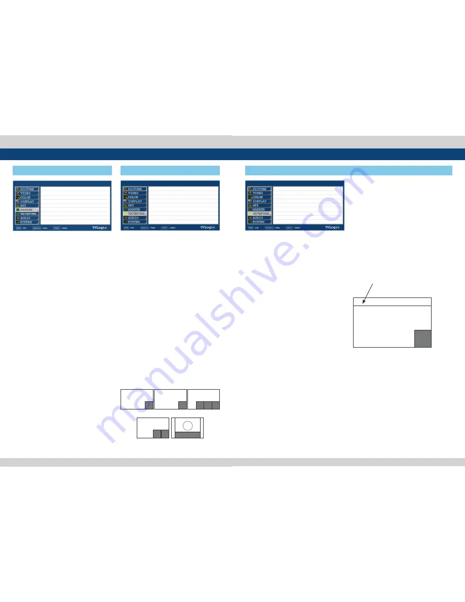
[6] MARKER
[7] WAVEFORM
5. Menu Operations
PAGE II >> PAGE I
USER MARKER H1
USER MARKER H2
USER MARKER V1
USER MARKER V1
MIN
MIN
MIN
MIN
PAGE I >> PAGE II
WAVEFORM/VECTOR
WAVEFORM INTENSITY
WAVEFORM TRANS
WAVEFORM SIZE
LINE WAVEFORM ENABLE
LINE POSITION SELECT
LINE POSITION DRAW
OFF
OFF
OPAQUE
NORMAL
OFF
0
OFF
<WAVEFORM>
<WAVE+VECTOR>
<VECTOR>
<YCbCr/RGB>
<WIDE Y>
WAVE
FORM
WAVE
FORM
VEC
TOR
VEC
TOR
Y/R
WAVEFORM
Cb/G Cr/B
XVM-177A
SDI A
[7] WAVEFORM
5. Menu Operations
PAGE I >> PAGE II
WAVEFORM/VECTOR
WAVEFORM INTENSITY
WAVEFORM TRANS
VECTOR GAIN X 4
LINE WAVEFORM ENABLE
LINE SELECT POSITION
LINE SELECT DRAW
WAVEFORM COLOR
OFF
OFF
OPAQUE
NORMAL
OFF
0
OFF
GREEN
●
WAVEFORM INTENSITY
- Used to control the brightness of the
WAVEFORM/VECTOR display.
- Available values are between 0 ~ 30. The
higher the number the brighter the
Waveform will be.
●
WAVEFORM TRANS
- Used to control the transparency level of the
WAVEFORM/VECTOR.
- Available values are OPAQUE and TRANS.
* If the option is set to OPAQUE, the main OSD
will overlap with the WAVEFORM/VECTOR.
However, it will automatically display it as
transparent and goes back to opaque if the
main OSD disappears.
●
VECTOR GAIN X4
- Used to increase the value of the Vectorscope.
●
LINE SELECT ENABLE
- Used to select specific Vertical Line for
Waveform/Vectorscope.
●
LINE SELECT POSITION
- In WAVEFORM/VECTOR, use the Up/Down
button to select User’s desired line.
●
LINE SELECT DRAW
- ON/OFF the line indication for line select
feature.
- Activates only when the LINE SELECT ENABLE
feature is enabled.
- When this item is set to OFF, the Line
Waveform still displays if LINE WAVEFORM is
enabled.
●
WAVEFORM COLOR
- This item cselects the color of Waveform/
Vectorscope.
- Available options are WHITE and Green.
Position changes if the value
changes in LINE SELECT option
and the waveform of the selected
position displays.
WAVEFORM/VECTOR : WAVEFORM
LINE POSITION SELECT : ON
LINE POSITION DRAW : ON
WAVE
FORM


