background image

30  4K LCD Monitor

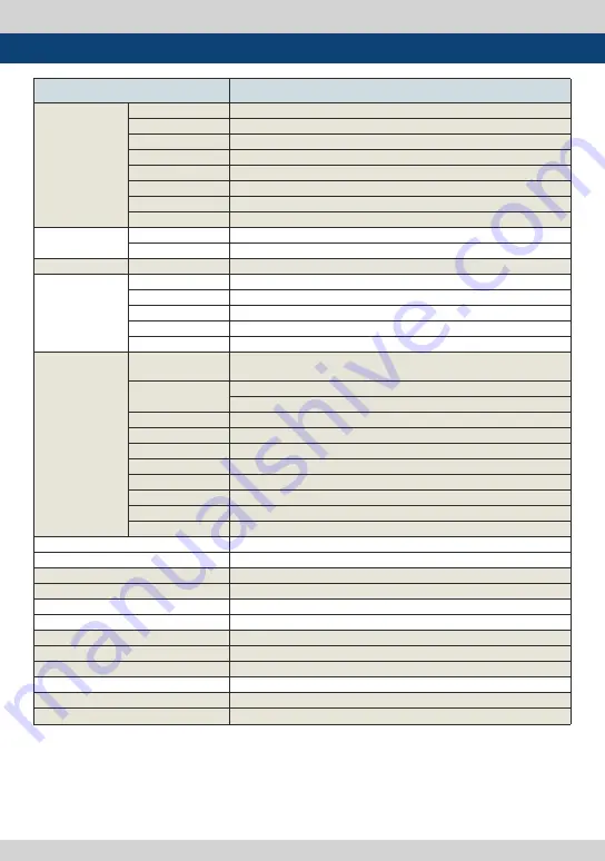
7. Product Specifications

* The specification above may be changed without notice.

LUM-242G

LCD

Size

23.8”

Resolution

3840 X 2160 (16:9)

Pixel Pitch

0.13725(H) X 0.13725(V) mm

Color Depth

1.07B Colors (A-FTC 10bit) 

Viewing Angle

H : 178 degrees / V : 178 degrees

Luminance of white

540 cd/ m

2

 (Center)

Contrast Ratio

1200 : 1

Display Area

527.04(H) X 296.46(V) mm

Input Connector

1 X HDMI

HDMI Input

4 X BNC

12G-SDI A/B,  3G-SDI C/D Channel Input

Output

4 X BNC

12G-SDI A/B,  3G-SDI C/D Channel (Active Through Out)

Input Signal

12G-SDI

12Gb/s

6G-SDI

6Gb/s

3G-SDI

2.970Gb/s

HD-SDI

1.485Gbps

HDMI

480p/720p/1080p/2160P

SDI Input Signal
Formats

SMPTE-425M-A/B

1080p(60/59.94/50/30/29.97/25/24/23.98/30sF/29.97sF/25sF/24sF/23.98sF) 
1080i(60/59.94/50)

SMPTE-274M

1080i (60/59.94/50)
1080p (30/29.97/25/24/24sF/23.98/23.98sF)

SMPTE-296M

720p (60/59.94/50)

SMPTE-260M

1035i (60/59.94)

SMPTE-125M

480i (59.94)

ITU-R BT.656

576i (50)

SMPTE ST 2036-1:2009  3840×2160(23.98/24/25/29.97/30/50/59.94/60p)
SMPTE ST 2048-2:2011  2048x1080(23,98/24/25/29.97/30p/psf, 47.95/48/50/59.94/60p)
SMPTE ST 2081

3840x2160 (30/25/24p)

SMPTE ST 2082

3840x2160 (60/50/30/25/24p)

Audio In

Embedded Audio / Analog Stereo (Phone Jack)

Audio Out

Internal Speaker (Stereo) / Analog Stereo (Phone Jack)

Power

DC 24V / AC100~240V(50~60Hz)

Power Consumption (Approx.)

115 Watts(Max)

Operating Temperature

0

℃ 

to 35

 (32

 to 95

Storage Temperature

-20

 to 60

 (-4

 to 140

Main Body Dimensions (mm/inch)

552.48 x 360.4 x 95.9 (21.75 x 14.18 x 3.77)

Main Body Dimensions with stand (mm/inch)

586.13 x 388.2 x 150 (23.07 x 15.28 x 5.90)

Box Dimensions (mm/inch)

555 X 450 X 280 (21.85 X 17.72 X 11.02) 

Weight

10.5kg / 23.14lbs

Basic Accessories

AC Power Cord, Stand 

Optional Accessories

Rack Mountable Kit, ND Filter, Carrying Case, V-mount, G-mount

Summary of Contents for LUM-242G

Page 1: ...Multi Format 4K LCD Monitor LUM 242G Operation Manual_V1 0 ...

Page 2: ......

Page 3: ...e harmful interference to radio communications Operation of this equipment in a residential to correct the interference at his own expense CAUTION Change or modifications not expressly approved by the manufacturer responsible for compliance could void the user s authority to operate the equipment Disposal of Old Electrical Electronic Equipment Applicable in the European Union and other European co...

Page 4: ...oving covers can expose you to high voltage and other dangerous conditions Request a qualified service person to perform servicing If any of the following conditions occurs unplug the power cord from the AC outlet and request a qualified service person to perform repairs a When the power cord or plug in damaged b When a liquid was spilled on the product or when objects have fallen into the product...

Page 5: ...vice Obstacles can cause electrical changes if there is a partition in the middle or in the wall Exposure to radio interference from medical equipment microwave ovens wireless LAN devices etc with the same frequency band When relocating the product placed on a cart it must be moved with the utmost care Sudden stops excessive force and uneven floor surface can cause the product to fall from the car...

Page 6: ...ng temperature Remote control function This product can simply be remote controlled by using parallel switch RS422 protocol support This product supports protocols provided by TVLogic Ethernet USB support Supports Ethernet and USB connection for program download monitor control and color calibration HDMI 2 0 support 1 x HDMI 2 0 input is available without additional equipment SDI 3G support Suppor...

Page 7: ...T LED POWER AUDIO OUT USB SCAN ENTER MENU EXIT RS 422 OUT SDI IN A D SDI OUT A D DC IN AC IN RS 422 IN DC OUT LAN REMOTE HDMI AUDIO IN HDMI SDI SINGLE 2 SDI QUAD F5 F4 F3 F2 F1 INFO VIDEO RANGE B LIGHT MARKER ASPECT LED POWER AUDIO OUT USB SCAN ENTER MENU EXIT RS 422 OUT SDI IN A D SDI OUT A D DC IN AC IN RS 422 IN DC OUT LAN REMOTE HDMI AUDIO IN ...

Page 8: ...ctivates in the order BLUE ONLY MONO BLUE ONLY Used to remove red and green from the input signal and display the screen only under a blue signal MONO Used to remove all colors from the input signal and display the screen only under white and black signal 2 H V DELAY Used to check horizontal and vertical sync simultaneously by moving the screen up down left right In this mode the brightness of ima...

Page 9: ...menu activation and also to increase decrease the value of the selected feature Press the Knob to confirm a chosen value or mode May also be used to control the Brightness Contrast Volume value during the OSD menu inactivation Turn the Knob to the left right to adjust the value OPERATE Lamp Indicates condition and power status of unit Light turns off when the power is disconnected Standby mode is ...

Page 10: ...nput signal LAN Used to control the monitor with a protocol provided by TVLogic AC IN 100 240V AC 50 60Hz WARNING When using the product make sure to ground whenever possible before connecting the input signal cable in order to prevent any possible damage to the product or connected devices The damage may include signal noise malfunction of main board or display panel And the connected devices suc...

Page 11: ...the KNOB to the left right 3 Press the KNOB button to select a menu and move to a sub menu by turning the KNOB to the left right 4 Press the KNOB button to select the desired sub menu The selected sub menu s font color will be highlighted 5 Press the KNOB or MENU button to save the new value after adjusting the value with the KNOB button The changed font color will be returned to default 6 Press t...

Page 12: ...ontrol Gamut Warning C Temp Color Temp Gain Red Gain Green Gain Blue Bias Red Bias Green Bias Blue Color Copy GPI PIN1 PIN8 Monitor ID DHCP IP Address Subnet Mask Gateway Port No Network settings apply UMD Display UMD Character UMD Character Color UMD B G trans UMD size MARKER Marker Center Marker Safety Area Fit Marker Marker Mat Marker Color Thickness User Marker H1 User Marker H2 User Marker V1...

Page 13: ...cus Assist Level Range Error Y Max Y Min AUDIO Level Meter Select Level Meter Display Level Meter Reference Level Meter Decay Time Level Meter Size Volume Em Audio Left Em Audio Right DISPLAY SET User Config Set Internal Pattern System Default S W Upgrade S W Upgrade Start Time Code Key Lock Key LED Closed Caption CC Info Decode Channel 608 Caption Service 708 OSD Position F1 Key Mapping F2 Key Ma...

Page 14: ...set the saturation level from 50 to 50 Aperture Used to set the sharpness level from 0 to 24 Aspect Used to change the various display ratio Only available in Single 3G Mode 3G Format Automatically detects when Payload signal appears in Normal Mode Selects input format for SDI 3G A B support NORMAL MODE A 444 10BIT_YCbCr A 444 10BIT_RGB A 444 12BIT_YCbCr A 444 12BIT_ RGB A 422 12BIT_YCbCr B 444 10...

Page 15: ...Standard Used to select the color and dynamic range of the screen Available options are HD UHD DCI P3 PQ HLG SLog3 and User1 2 3 Activates only in the User1 2 3 mode Video Range Used to select the range of digital video signal Full Range Input signal 0 255 8bit 0 1023 10bit When connecting the PC SDI Range Input signal 1 254 8bit 4 1019 10bit Narrow Input signal Y 16 235 CbCr 16 240 8bit Y 64 940 ...

Page 16: ...ivated only in User 1 2 3 mode and color area which is wider than display area of panel Gamut Warning Future Update Used to display warning when the input colors exceeds the permissible range of the panel color gamut Available modes are OFF and ON This menu is activated only in User 1 2 3 mode and color area which is wider than display area of panel C Temp Controls the color temperature Available ...

Page 17: ...sed to set Blue Gain level from 256 to 255 Adjusts the blue color of bright section Only available in User mode 2 COLOR 5 Menu Operations Bias Red Used to set Red Bias from 100 to 100 Adjusts the red color of dark section Only available in User mode Bias Green Used to set Green Bias from 100 to 100 Adjusts the green color of dark section Only available in User mode Bias Blue Used to set Blue Bias ...

Page 18: ...35 1 MARKER 1 85 1 4 3 MARKER CENTER MARKER SAFETY AREA 80 SAFETY AREA 85 SAFETY AREA 88 SAFETY AREA 90 SAFETY AERA 90 SAFETY AERA 93 SAFETY AERA 100 TALLY R TALLY G 3 GPI 5 Menu Operations This item activates inactivates the REMOTE function The user may designate a function for each pin and each pin s default setting is as follows The default settings are as follows PIN 1 SINGLE SDI PIN 2 2SI SDI...

Page 19: ...set UMD and ANC Available modes are OFF UMD and ANC UMD Displays user customized 8 characters on screen ANC Displays characters embedded in SDI signal UMD Character Used to customize the characters for Under Monitor Display Alphabets numbers and special symbols are available Maximum of 8 characters are available UMD character color Used to set the character color of UMD White Red Green Yellow Cyan...

Page 20: ...er type when the MARKER is displayed on the screen MARKER may only be activated by pressing the MARKER button on the bottom front of the monitor Available marker types are Off 16 9 4 3 4 3 ON AIR 15 9 14 9 13 9 1 85 1 2 35 1 1 85 1 4 3 4 3 ALT 14 9 16 9 ALT 14 9 16 9 ALT 4 3 and USER Center Marker Used to select the availability of the CENTER MARKER on the screen This function operates only after ...

Page 21: ...r H2 Used to set the position of the second horizontal marker line Displayed when MARKER menu is set to USER USER Marker V1 The item controls the position of the first user defined vertical marker line Marker option USER needs to be selected USER Marker V2 The item controls the position of the second user defined vertical marker line Marker option USER needs to be selected ...

Page 22: ...ntrol range varies according to the resolution of the input SDI signal PAL Min 17 Max 522 NTSC Min 23 Max 623 720p Min 26 Max 750 1080i Min 21 Max 1123 1080p Min 42 Max 1121 Control range varies according to the resolution of the input HDMI Analog signal Min 0 Max 600 5 Menu Operations 5 WAVEFORM FOCUS Waveform Display This function sets the Waveform and Vectorscope Activates in the order Off Wave...

Page 23: ... Y MIN C MAX and C MIN functions The values of Y MAX Y MIN C MAX and C MIN are indicated in WAVEFORM VECTOR Luma Y Zone Check Displays the Luma Y level of the input image in colors Can select between Color Pattern or Zebra Pattern When Y level of the pixel is under 0 16 the color diagonal line will be colored Green When Y level of the pixel is over 100 235 the color diagonal line will be colored R...

Page 24: ...r number means a longer display time for max value Level Meter Size Used to control the size of the Audio Level Meter Available modes are Small Small Translucent Normal Normal Translucent Large and Large Translucent In Small Normal and Large modes the level meter appears opaque In Small Translucent Normal Translucent Large Translucent modes the level meter appears semitransparent Volume Used to co...

Page 25: ...W Upgrade Start menu to start the USB memory search When the USB memory is detected the S W Upgrade Start menu becomes activated S W Upgrade Start Select the S W Upgrade Start menu to start the firmware upgrade Do not turn off the monitor while the upgrade is conducting Time Code Used to set the Time Code Available modes are OFF VITC and LTC Key Lock Used to lock all buttons except Power Input sel...

Page 26: ...tion This item controls the OSD position Available values are Center Top Right Bottom Right Bottom Left and Top Left F1 Key Mapping User can select the function for the F1 button F2 Key Mapping User can select the function for the F2 button F3 Key Mapping User can select the function for the F3 button F4 Key Mapping User can select the function for the F4 button F5 Key Mapping User can select the ...

Page 27: ... input signal SDI Payload ID Displays the values of the Byte 1 2 3 4 Video Standard Displays the standard of the Payload ID Byte 1 Sampling Displays the Sampling Structure information of the Payload ID Byte 3 Picture Rate Displays the Picture Rate of the Payload ID Byte 2 Scanning Method Displays the Interlace Progressive of the Payload ID Byte 2 Bit Depth Displays the Bit Depth information of the...

Page 28: ... Psf YCbCr 4 4 4 10 12bit RGB 4 4 4 10 12bit 3G SDI 2 Sample Interleave Dual link 4K 3840x2160 23 98 24 25 29 97 30 p YCbCr 4 2 2 10bit 4096x2160 23 98 24 25 29 97 30p YCbCr 4 2 2 10bit 3G SDI 2 Sample Interleave Square Quad link 4k 3840x2160 50 59 94 60p YCbCr 4 2 2 10bit 3840x2160 23 98 24 25 29 97 30 p YCbCr 4 4 4 10 12bit RGB 4 4 4 10 12bit 4096x2160 23 98 24 25 29 97 30p YCbCr 4 4 4 10 12bit ...

Page 29: ...0p 1920x1080 50 59 94 60i 1920x1080 50 59 94 60p RGB 4 4 4 8 10 12bit YCbCr 4 4 4 8 10 12bit YCbCr 4 2 2 12bit 800x600 60Hz 1024x768 60Hz 1280x1024 60Hz 1600x1200 60Hz VESA 3840x2160 23 98 24 25 29 97 30 4096x2160 23 98 24 25 29 97 30 RGB 4 4 4 8bit YCbCr 4 4 4 8bit 3840x2160 50 60p 4096x2160 50 60p RGB 4 4 4 8bit YCbCr 4 4 4 8bit 6 Video Support Resolution VIDEO SUPPORT RESOLUTION ...

Page 30: ... 1080p 30 29 97 25 24 24sF 23 98 23 98sF SMPTE 296M 720p 60 59 94 50 SMPTE 260M 1035i 60 59 94 SMPTE 125M 480i 59 94 ITU R BT 656 576i 50 SMPTE ST 2036 1 2009 3840 2160 23 98 24 25 29 97 30 50 59 94 60p SMPTE ST 2048 2 2011 2048x1080 23 98 24 25 29 97 30p psf 47 95 48 50 59 94 60p SMPTE ST 2081 3840x2160 30 25 24p SMPTE ST 2082 3840x2160 60 50 30 25 24p Audio In Embedded Audio Analog Stereo Phone ...

Page 31: ...4K LCD Monitor 31 MEMO ...

Page 32: ...32 4K LCD Monitor MEMO ...

Page 33: ...4K LCD Monitor 33 MEMO ...

Page 34: ...34 4K LCD Monitor MEMO ...

Page 35: ......

Page 36: ...53 802 서울특별시 금천구 가산동 345 4 에이스하이엔드 8차 12층 FOR MORE INFORMATION PLEASE VISIT http www tvlogic tv 12F ACE HIGH END 8 84 Gasan digital 1 ro Geumcheon gu Seoul 18590 KOREA TEL 82 70 8668 6611 FAX 82 2 6123 3201 E mail sales tvlogic co kr ...

Reviews: